


Ziroli 1/7 (120") B-25 B scale build
 08-15-2022, 06:49 PM
#126
Senior Member
Thread Starter

Working to close up the wings. In the Air Force we had a saying " Flexibility is the key to air power", I am definitely flexible, doing change after change.
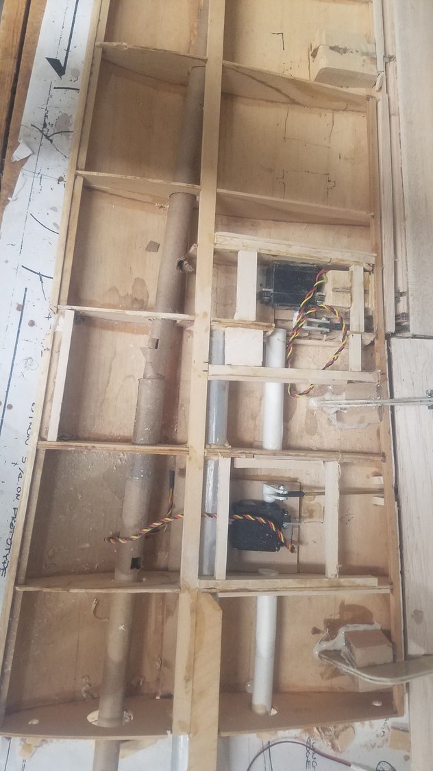
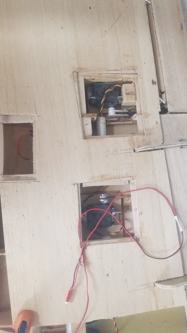
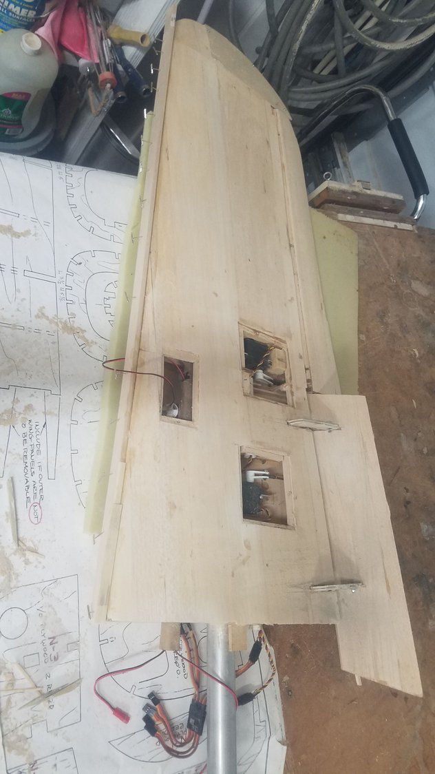
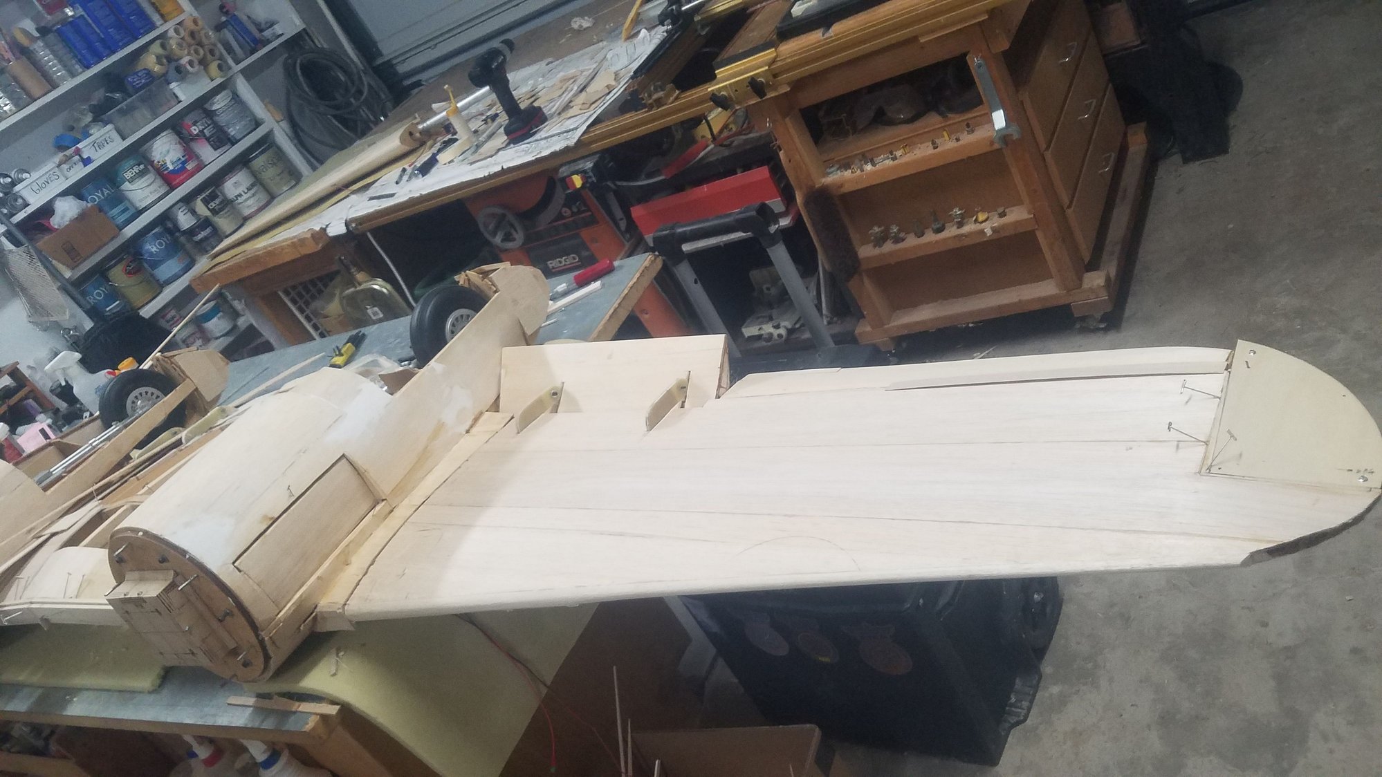
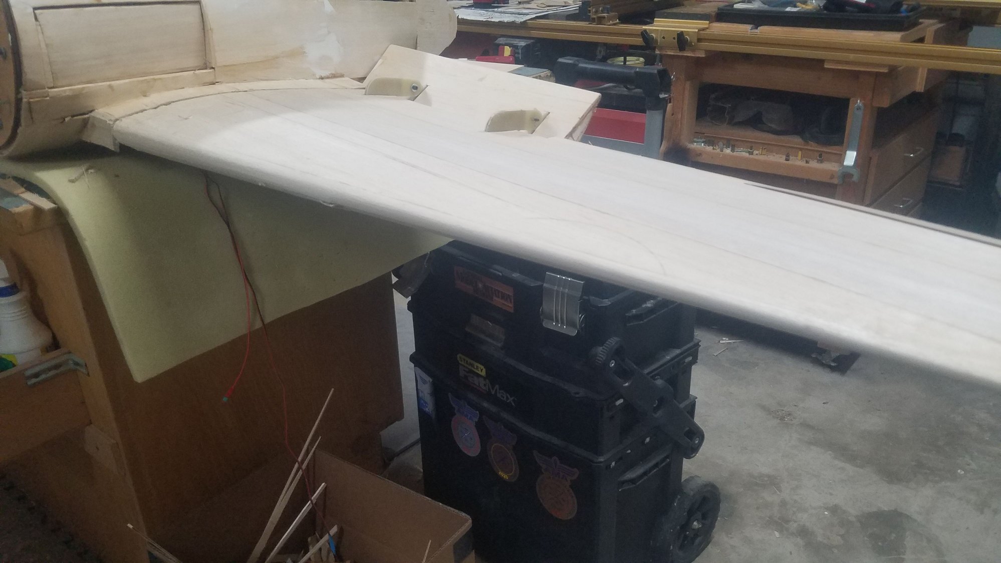
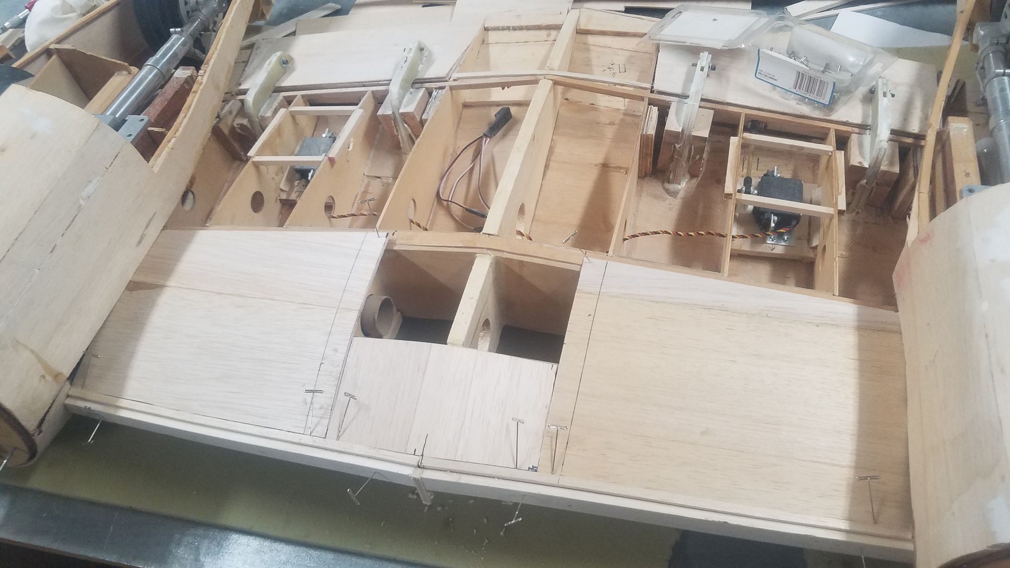
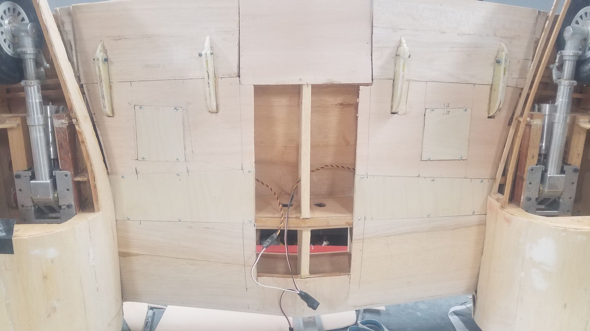
Installing access hatch bass wood structures. Stiffened some ribs which were cut. I added more glue area for the shin around the access structures. Access hatches will be 3/32" plywood and screwed down to the hatch structure.
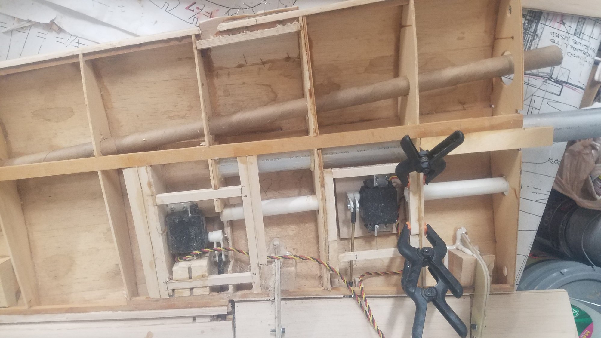
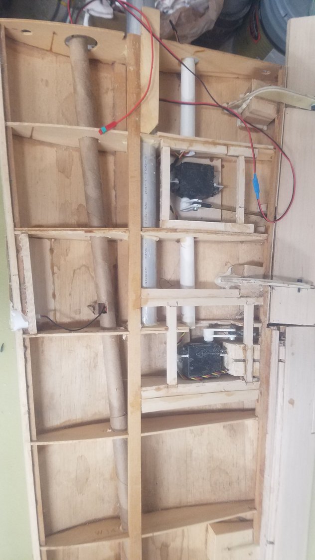
This shows where I changed the plan to feed in the wire (flexibility). Now the servos will use the new wire tubes (white) and the nav. and landing lights will use the front wire tube (brown). I am thinking I will use 2 lead connecters, but maybe not, as I see how the wings mount to the center section. I like to keep the connectors to as few as possible and a 4 lead connect sounds better to me if I can make it work in the center section.
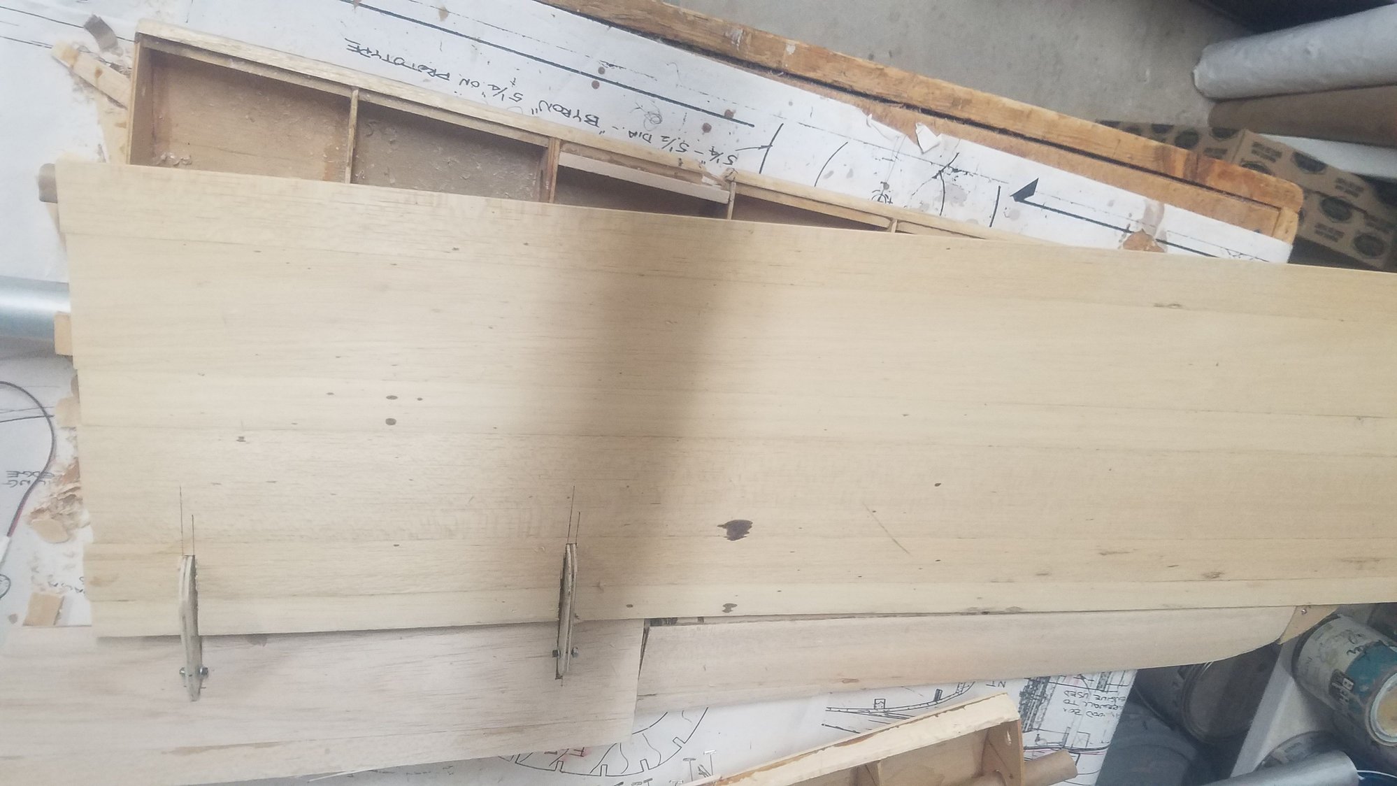
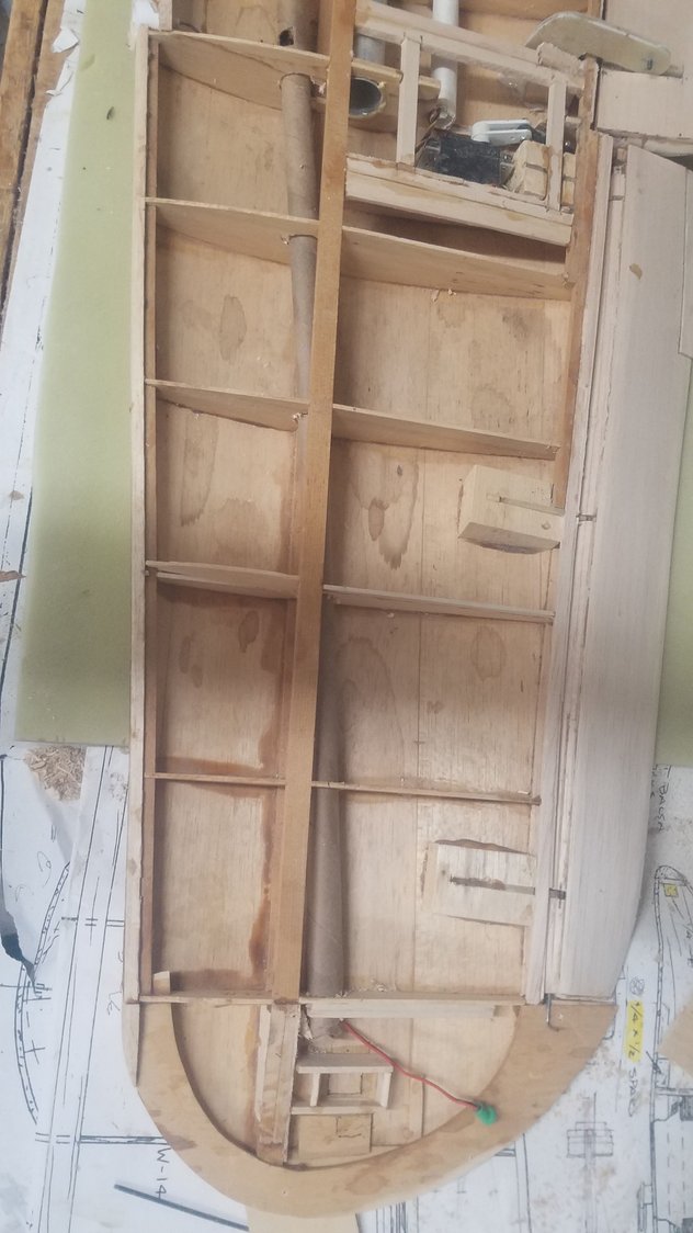
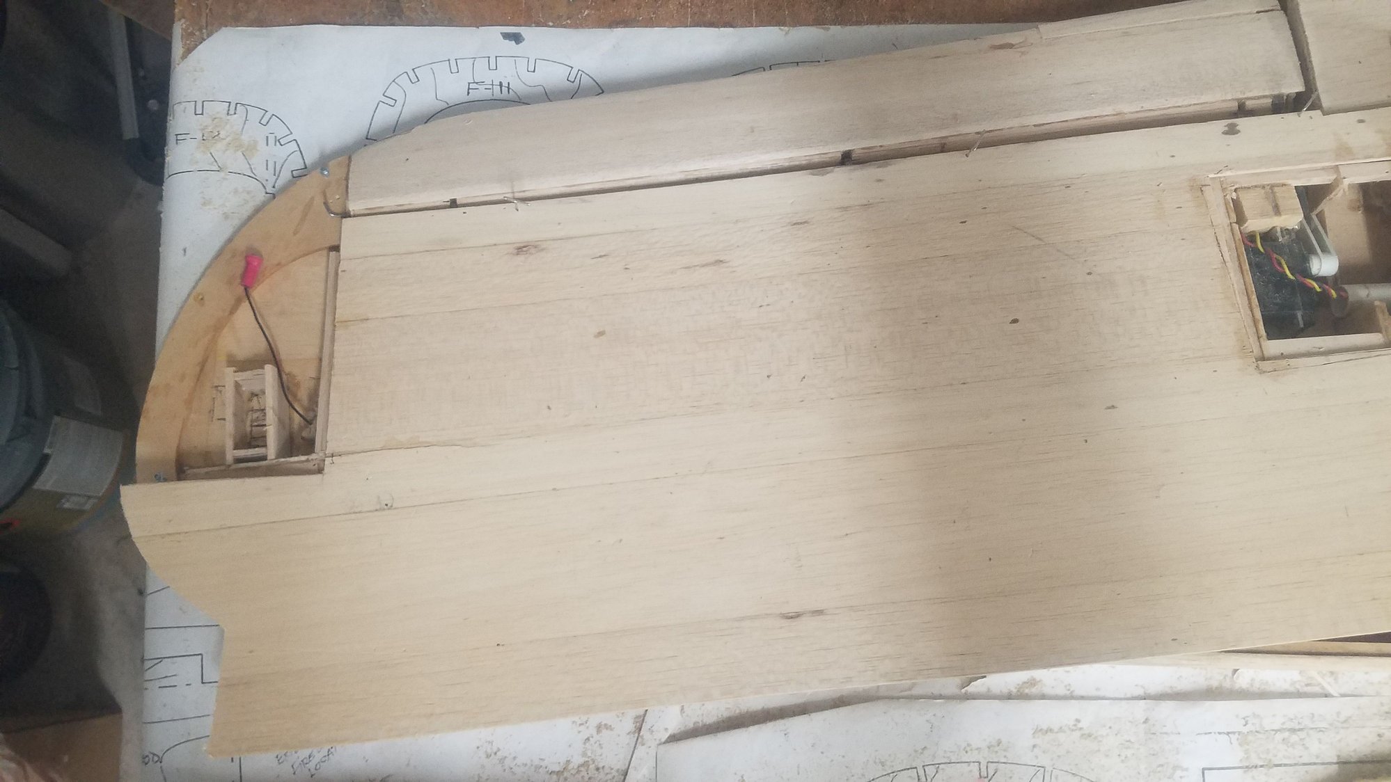
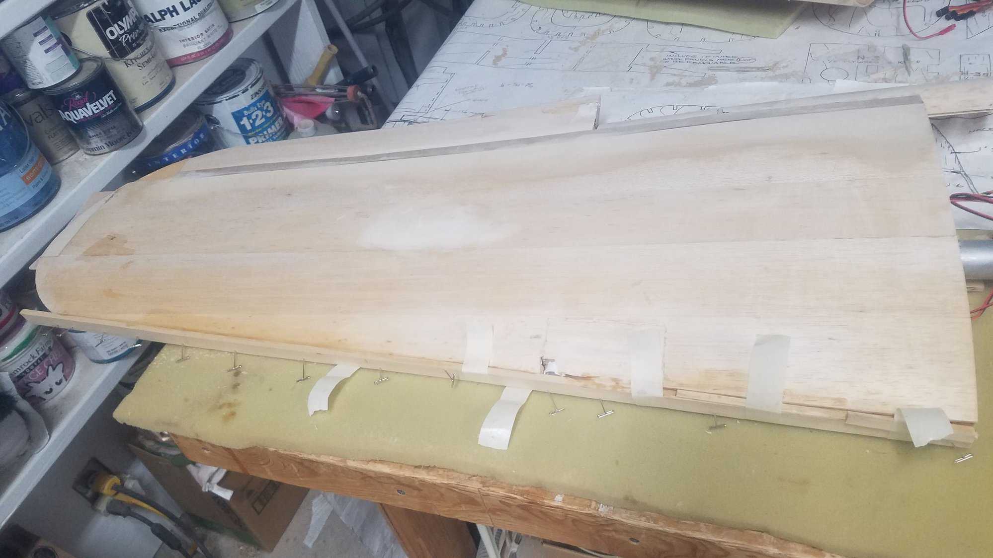
Dry fit of skin, however, I have more internal things to get done before I glue it up. I am really looking forward to closing up the wings.
Installing access hatch bass wood structures. Stiffened some ribs which were cut. I added more glue area for the shin around the access structures. Access hatches will be 3/32" plywood and screwed down to the hatch structure.
This shows where I changed the plan to feed in the wire (flexibility). Now the servos will use the new wire tubes (white) and the nav. and landing lights will use the front wire tube (brown). I am thinking I will use 2 lead connecters, but maybe not, as I see how the wings mount to the center section. I like to keep the connectors to as few as possible and a 4 lead connect sounds better to me if I can make it work in the center section.
Dry fit of skin, however, I have more internal things to get done before I glue it up. I am really looking forward to closing up the wings.
 08-17-2022, 08:48 PM
#127
Senior Member
Thread Starter
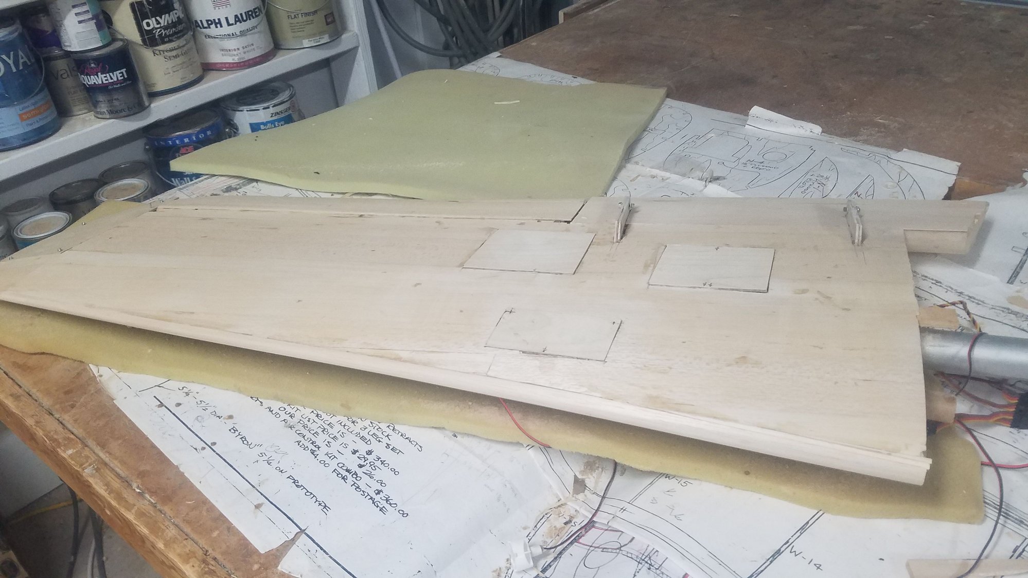
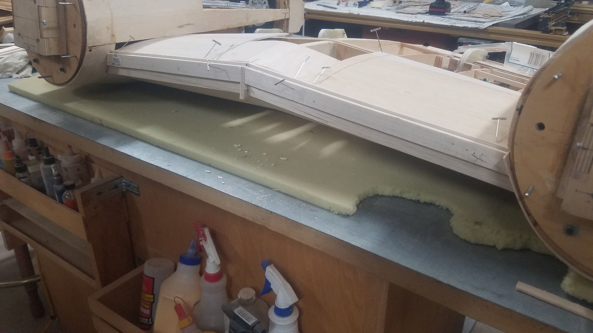
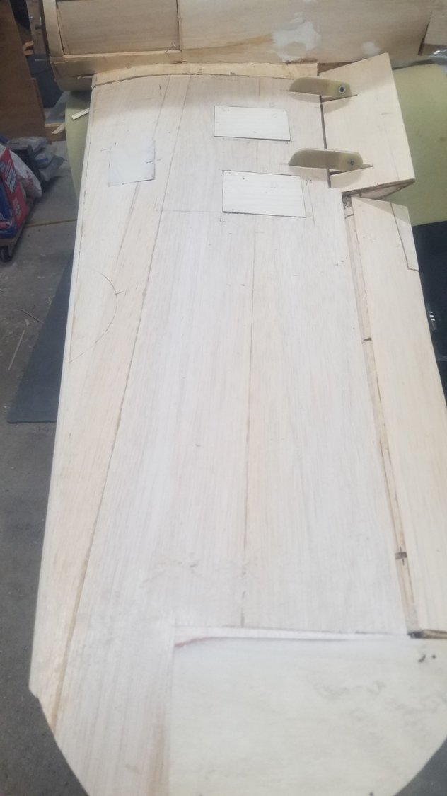
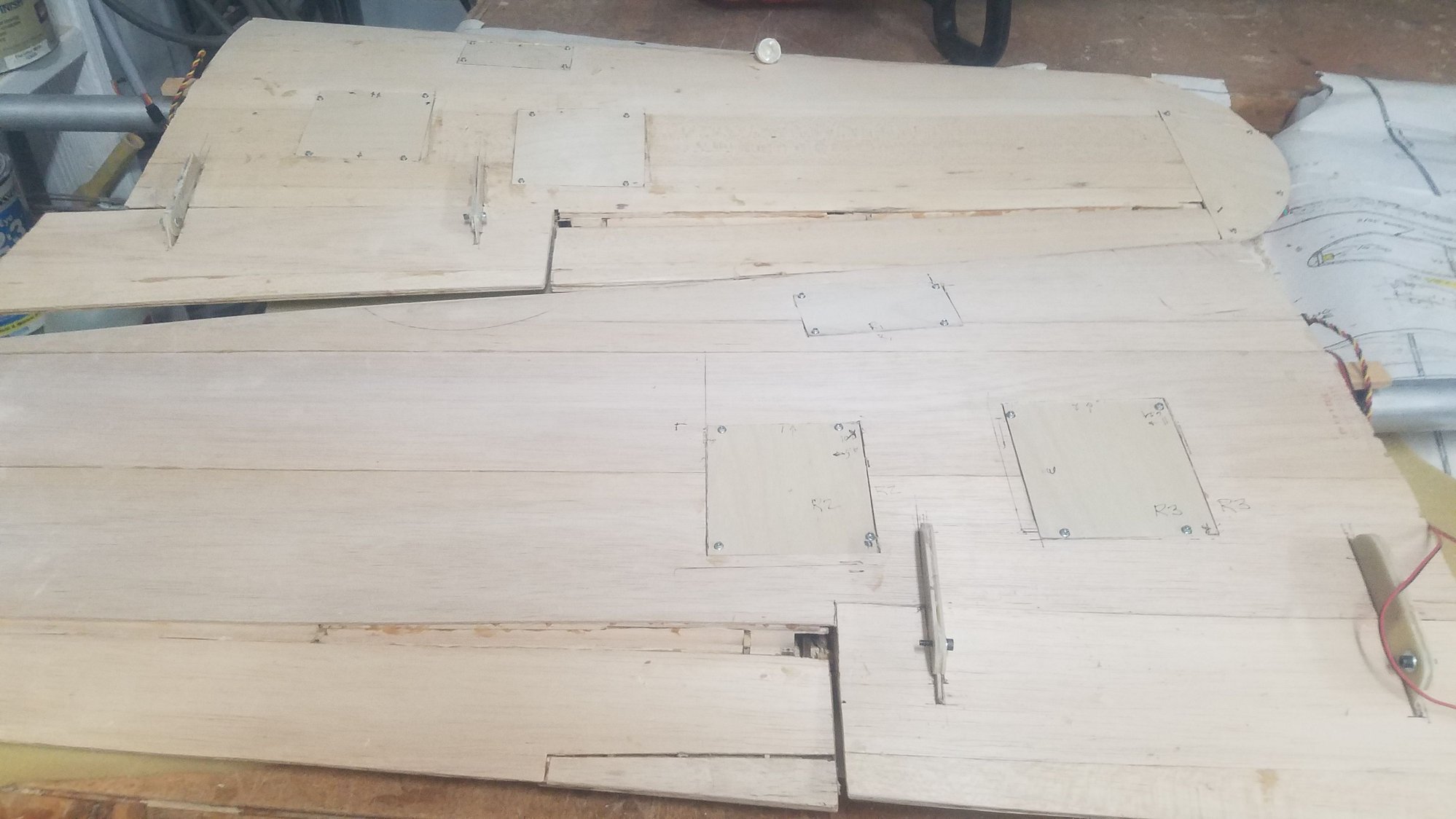
Skin dry fit and using pins to locate it. Decided to use the access covers as cutting guides for the skin. They are placed on top of the skin and screwed down using existing predrilled screw holes to locate the covers.
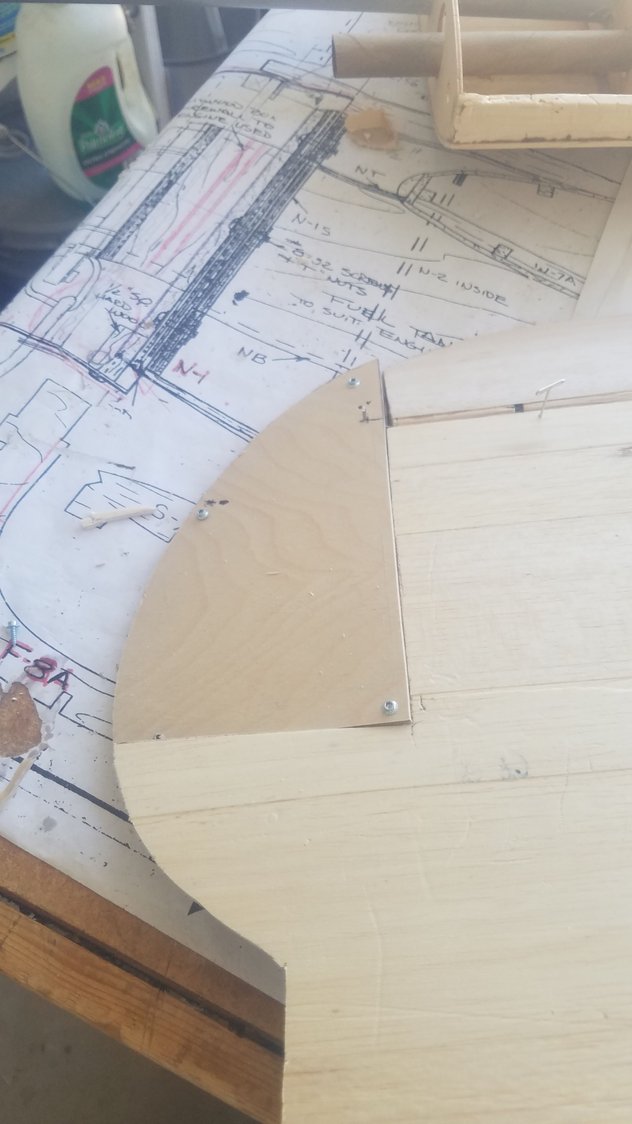
Cutting in access covers
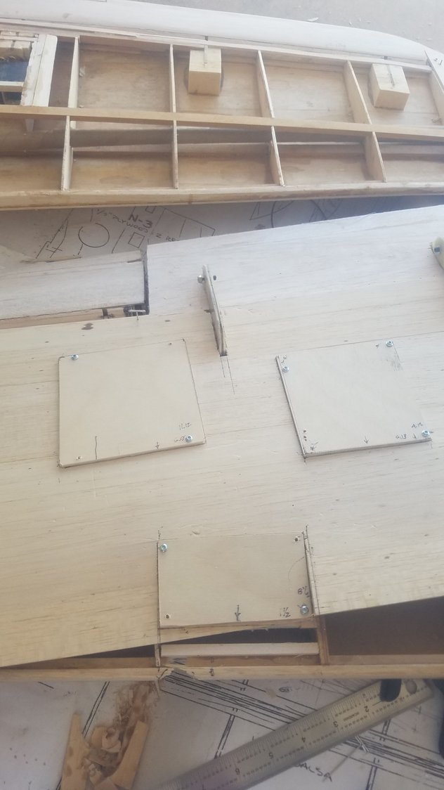
Access covers located and used as cutting guides
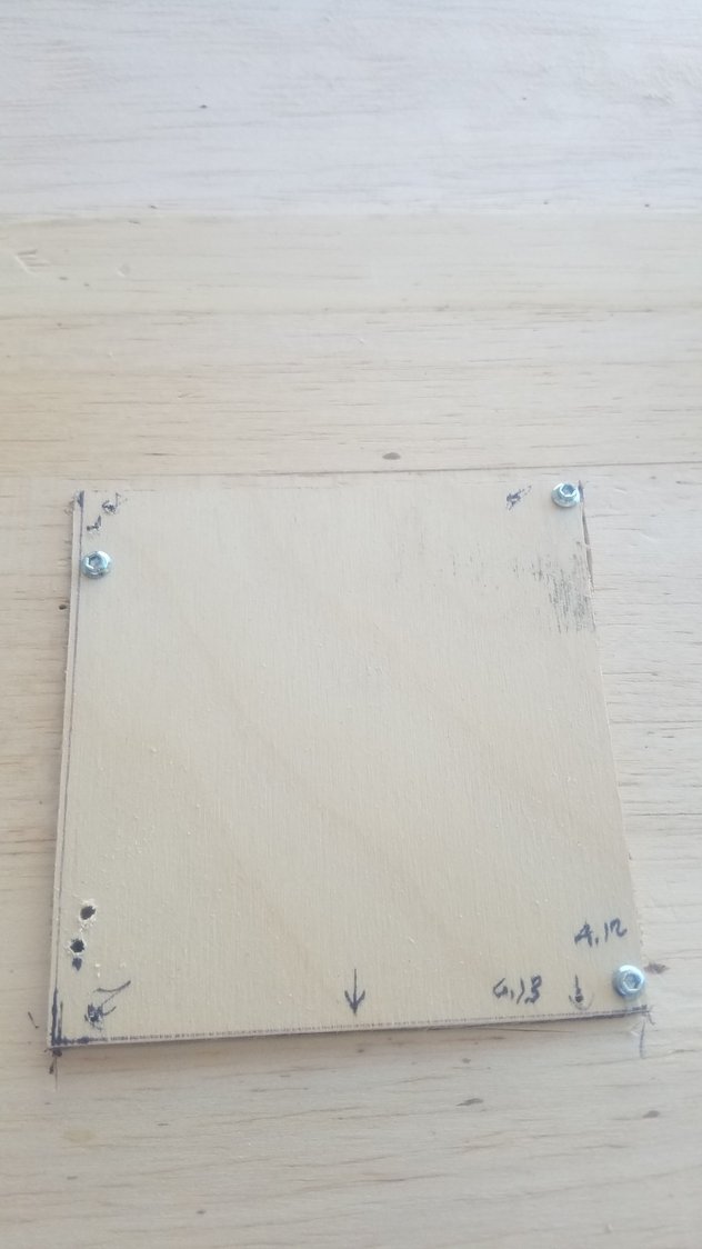
Using predrilled holes to locate access covers. Note, the dimensions on the cover to spot the predrilled holes.
Cutting in access covers
Access covers located and used as cutting guides
Using predrilled holes to locate access covers. Note, the dimensions on the cover to spot the predrilled holes.
08-25-2022, 06:27 PM
#128
Senior Member
Thread Starter
Had to take days to recover from a reaction to the second Shingles shot. All back to normal now and while I was down, I ordered more balsa, ply, Robart stuff for the gear, connectors, and the scale cockpit. All have now arrived so the work resumes. Put the lights in the wings and with the new 3/32 ply made the hatch covers to match the balsa skin. Now after long last I am closing the wing. Also placed the receiver/servo batteries and install some of the leading-edge material.
Stringing the nav and landing light.
Built the light box for the nav lights in the wing tip. Will have to make the lens, cut the skin and glue them in.
Servos wired in.
Nav light to be installed in the box after lens is made and installed.
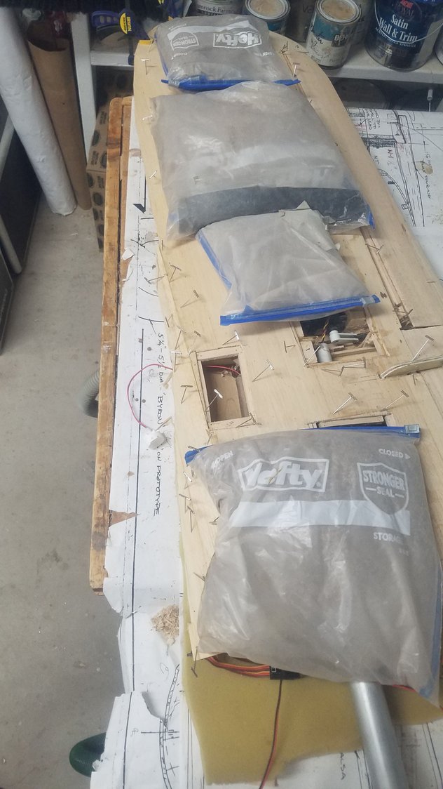
Finally closing the left wing, right wing to go.
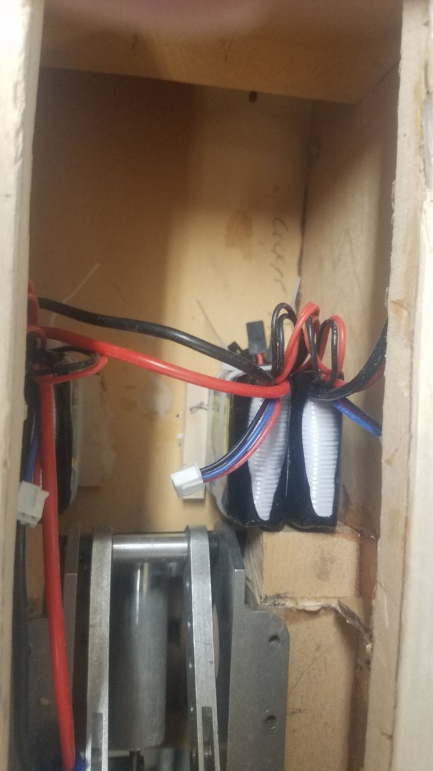
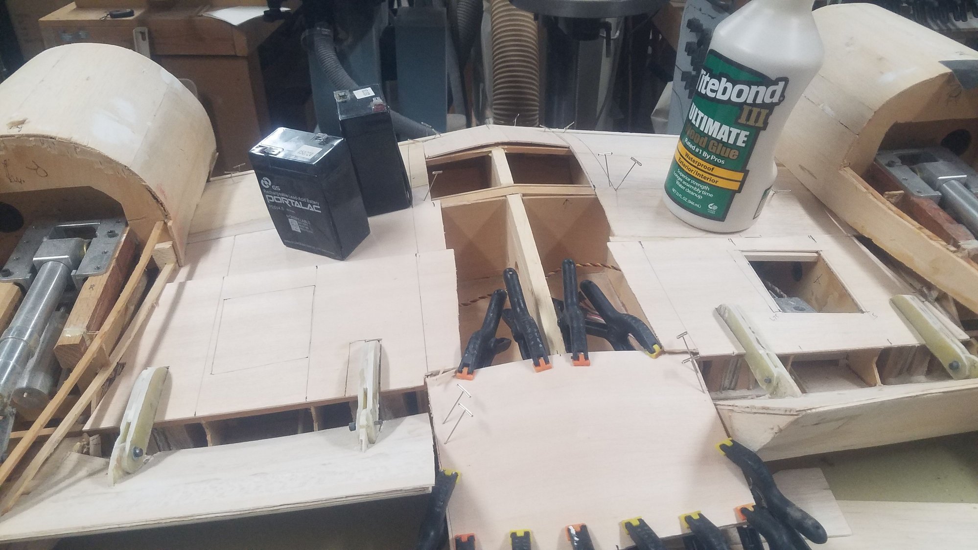
Installed the receiver/servo batteries as far forward as possible. I hope to keep the amount of lead shot at a minimum. These are 4 LIFE 3200 batteries, 2 per receiver for redundancy.
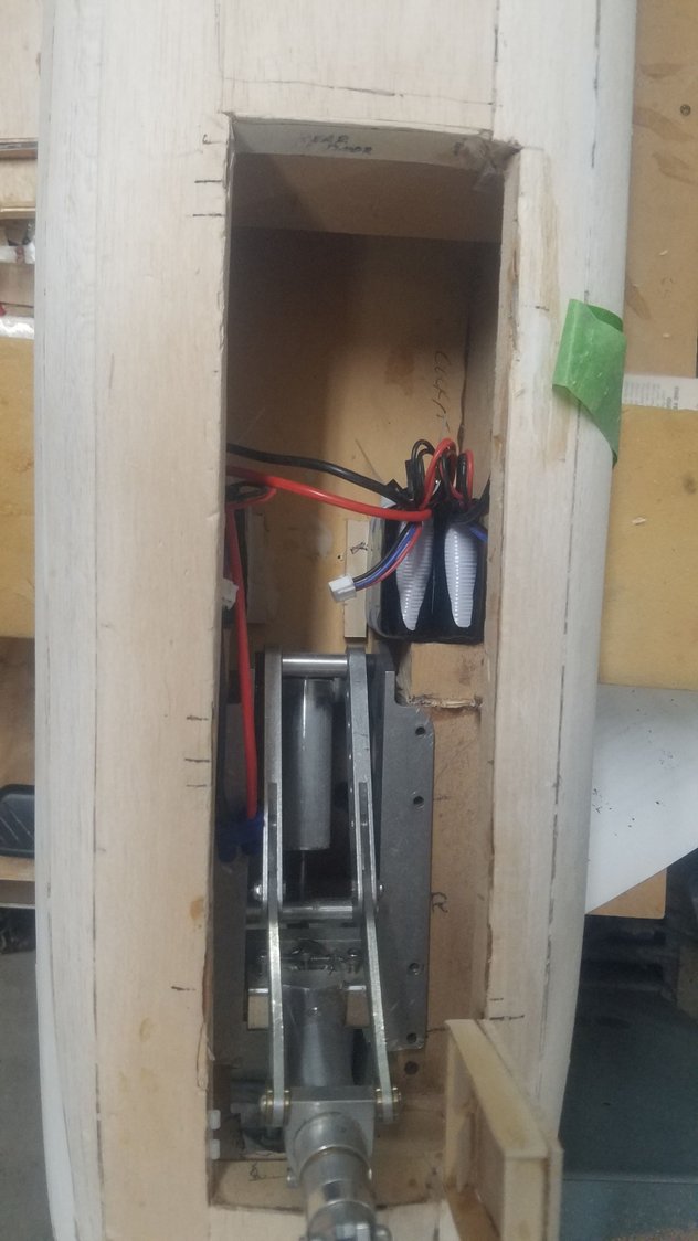
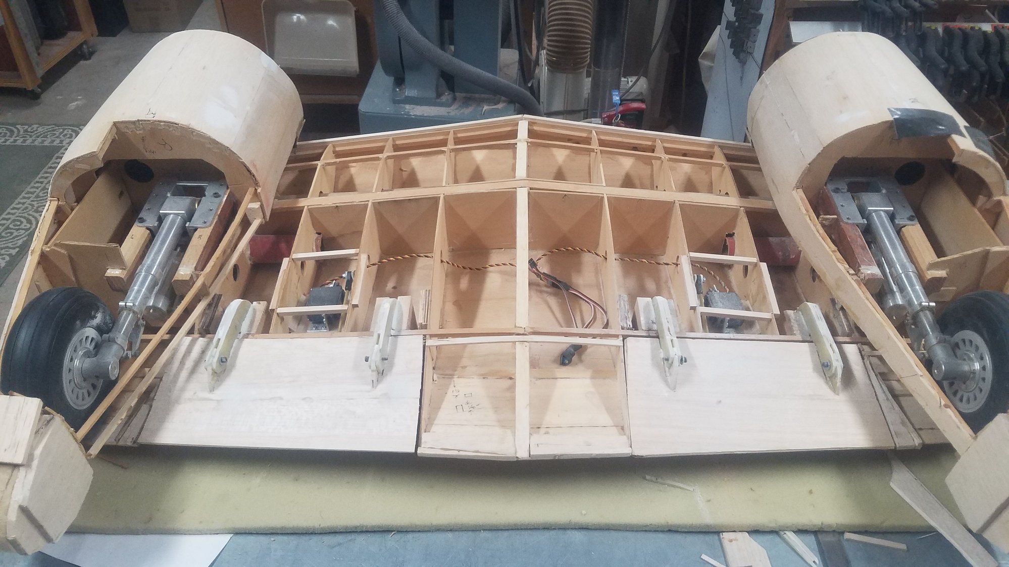
2 Batteries per side in the nose gear well.
Starting leading edge install.
More leading edge on center section.
Stringing the nav and landing light.
Built the light box for the nav lights in the wing tip. Will have to make the lens, cut the skin and glue them in.
Servos wired in.
Nav light to be installed in the box after lens is made and installed.
Finally closing the left wing, right wing to go.
Installed the receiver/servo batteries as far forward as possible. I hope to keep the amount of lead shot at a minimum. These are 4 LIFE 3200 batteries, 2 per receiver for redundancy.
2 Batteries per side in the nose gear well.
Starting leading edge install.
More leading edge on center section.
08-31-2022, 08:37 AM
#129
Senior Member
Thread Starter
Took a few days off again to get to know the new JR Elite radio that just showed up. Programming software and manual are not up to speed yet, but the radio performs extremely well.
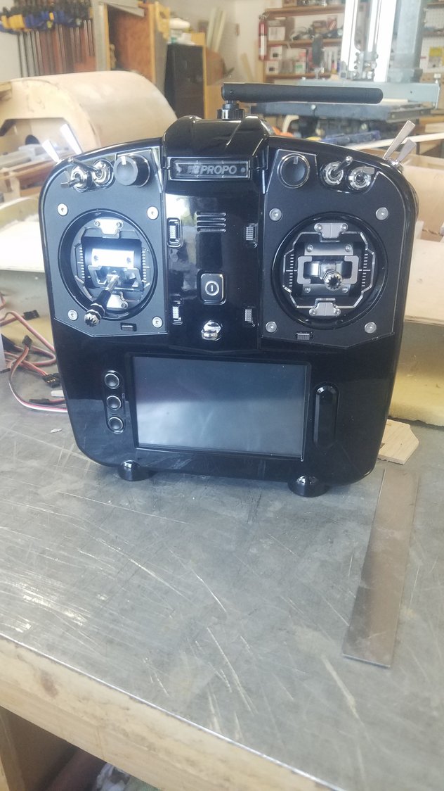
Nice radio. Took several days to learn programming and setup to use on my testbed 83" Stik. JR has some work to do to get the manual and the radio to match and all functions operational, hopefully soon.
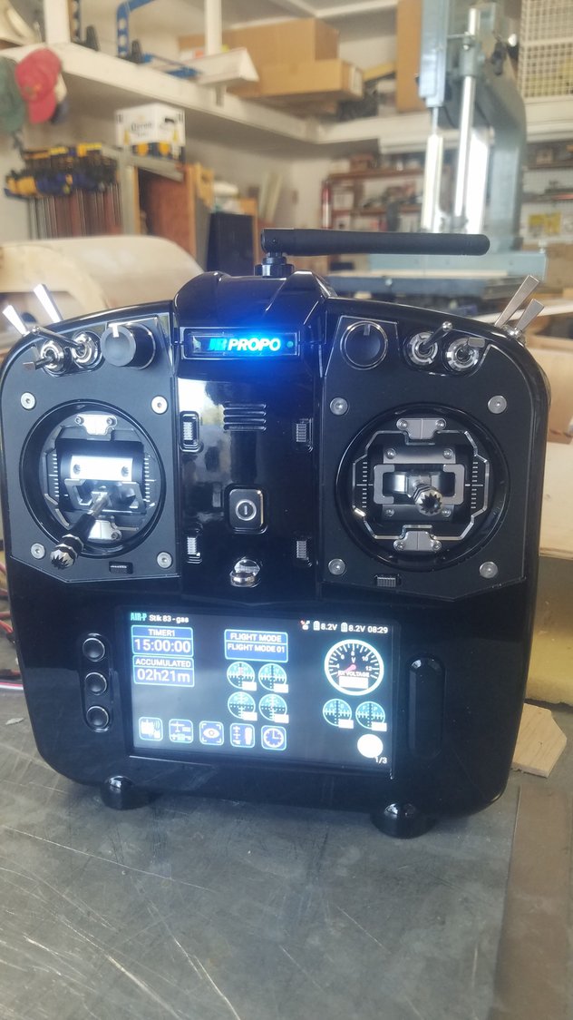
Flew with it on Monday and it feels very strong and smooth. It is a real pleasure to fly with this radio. It is smooth as silk.
Nice radio. Took several days to learn programming and setup to use on my testbed 83" Stik. JR has some work to do to get the manual and the radio to match and all functions operational, hopefully soon.
Flew with it on Monday and it feels very strong and smooth. It is a real pleasure to fly with this radio. It is smooth as silk.
08-31-2022, 07:37 PM
#130
Senior Member
Thread Starter
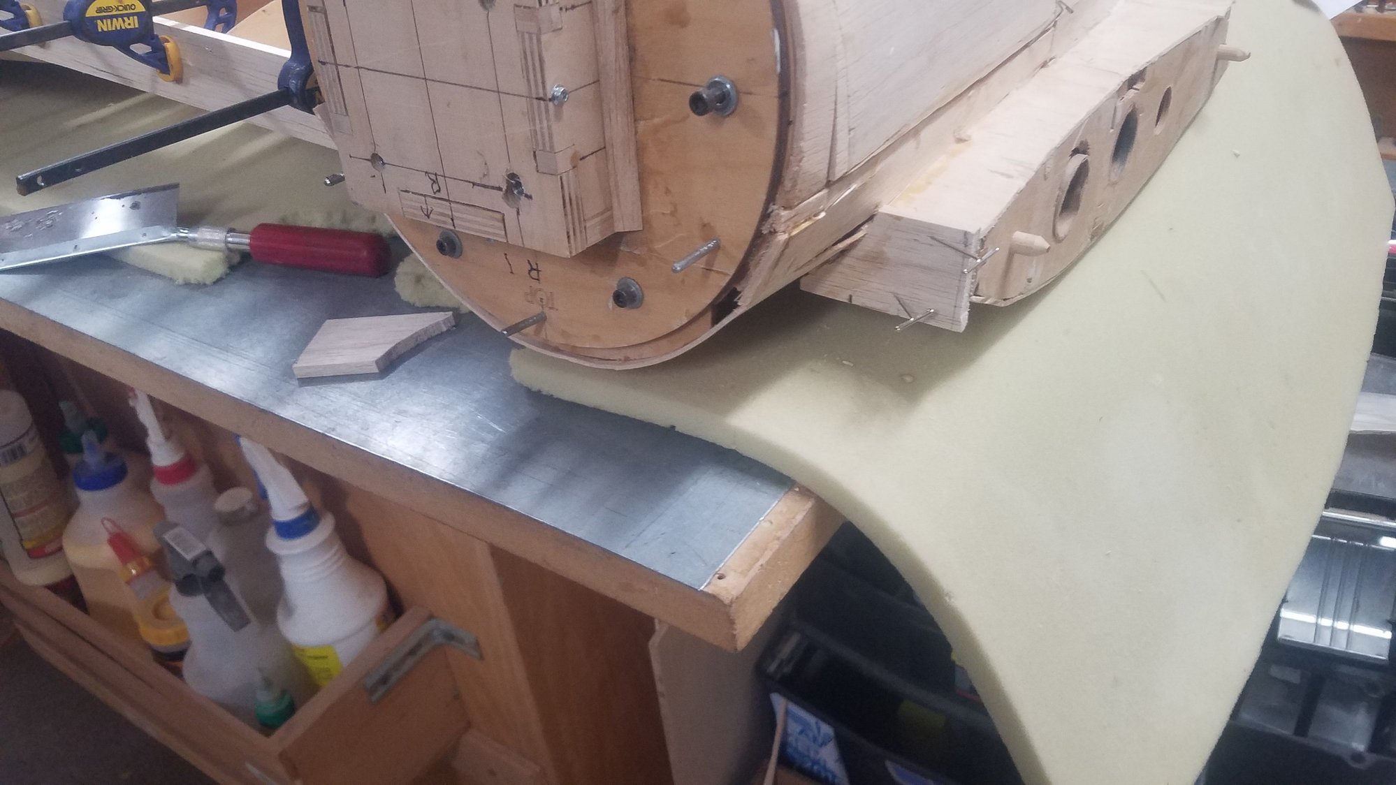
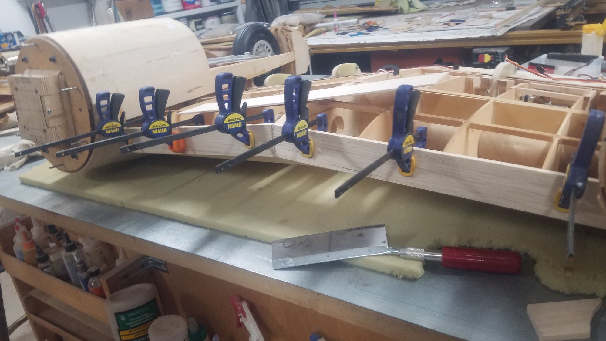
Closed up wing and glued on leading edge. Close up center section next.
Rough leading edge applied.
Leading edge on other wing. Will have to trim the raw stock down and sand to shape on both wings.
Center section is next to be closed. I wonder if I should leave the center under the fuselage open for connections. I don't think I need the skin there for strength. Actually, a lot of wiring and air lines need to be run first. I will send some time figuring what needs to go where.
Last edited by rossmick; 08-31-2022 at 07:43 PM.
09-02-2022, 06:37 PM
#131
Senior Member
Thread Starter
Just one of the 'push ahead' days as small mistakes caused a lot more work to make it right. Leading edges done on wings, access hatches to be finished and some center section work dry fitted. Got satellite radios installed and bound to the Elite.
Leading edge matchup with center section. Needs access hatches cut in.
Better view of leading edge
Leading edge and hatches installed but hatches not screwed in. I am considering another hatch at the wing root for access to the connectors.
Center section leading edge dry laid up.
Dry install of front skin on center section. Will leave center section in the middle open for access to fuselage for air lines and servo leads.
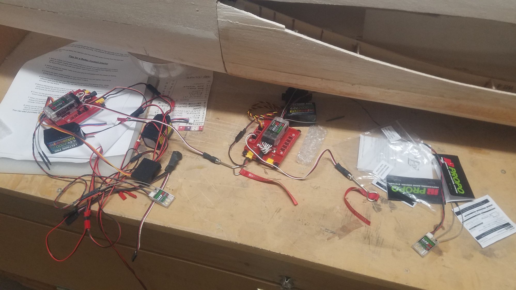
Satellite receivers installed and bound to the Elite radio, should not have a problem with reception. I think on the next build I will use Xbus rather than the two radios and PWM. Problem I see is the wire size to handle the multiple servos current draw to the receiver. If you go to digital servos, you can draw 4-5 amps per servo causing a 50 amp or more flow through the receiver. I need to find out which receiver handles that amount of current. Xbus costs need to be compared as well. Took a quick look at Xbus and I see that the servos are powered by a power hub from a separate battery. This is the same concept as the Smart Fly board but uses just the Xbus slot where the Smart Fly board uses all the receiver slots.
Leading edge matchup with center section. Needs access hatches cut in.
Better view of leading edge
Leading edge and hatches installed but hatches not screwed in. I am considering another hatch at the wing root for access to the connectors.
Center section leading edge dry laid up.
Dry install of front skin on center section. Will leave center section in the middle open for access to fuselage for air lines and servo leads.
Satellite receivers installed and bound to the Elite radio, should not have a problem with reception. I think on the next build I will use Xbus rather than the two radios and PWM. Problem I see is the wire size to handle the multiple servos current draw to the receiver. If you go to digital servos, you can draw 4-5 amps per servo causing a 50 amp or more flow through the receiver. I need to find out which receiver handles that amount of current. Xbus costs need to be compared as well. Took a quick look at Xbus and I see that the servos are powered by a power hub from a separate battery. This is the same concept as the Smart Fly board but uses just the Xbus slot where the Smart Fly board uses all the receiver slots.
Last edited by rossmick; 09-02-2022 at 07:24 PM.
09-05-2022, 09:49 AM
#132
Senior Member
Thread Starter
Access hatches cut in and mistakes fixed.
Center section dry layup of skin. Tail section glued in with added web pieces under rear spar. Need to work out wire and airline locations and system before I glue this up.
09-06-2022, 06:30 PM
#133
Senior Member
Thread Starter
I've been managing 3 - 4 hours a day while working about 5 days a week. So, 20 hours per week makes for a long build time on this plane. Looks like it will be many more months to finish it too just a prime coat finish. Then I see at least another several months to put on the panel lines and rivets. Large airplanes take a very long time to complete.
Center section leading edge completed and access panels screwed in.
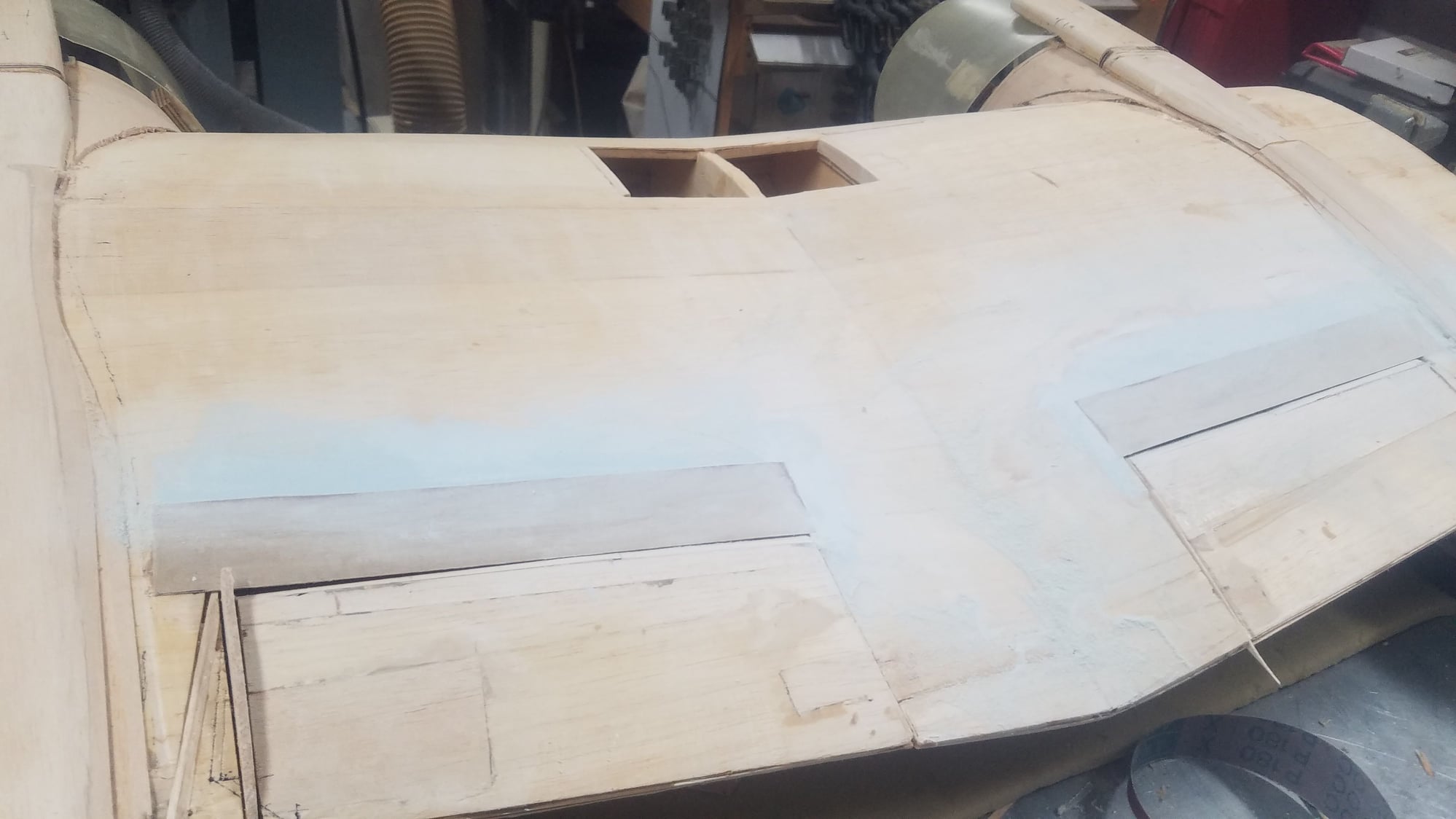
Access hatches screwed in on the wings. Now works starts on the nacelles and the main gear doors. Also, will modify the center section flaps to be per scale shape.
Center section leading edge completed and access panels screwed in.
Access hatches screwed in on the wings. Now works starts on the nacelles and the main gear doors. Also, will modify the center section flaps to be per scale shape.
09-12-2022, 06:07 PM
#134
Senior Member
Thread Starter
Had many other choirs to do, so had to lay off the 25 for a few days. Been figuring out a manual way to open the gear doors that stay open when the gear is extended. Servos will handle the doors that open and then close with gear extended and the door that stays open will be operated by the gear. Moving on to finishing the cowls and then the main gear doors.
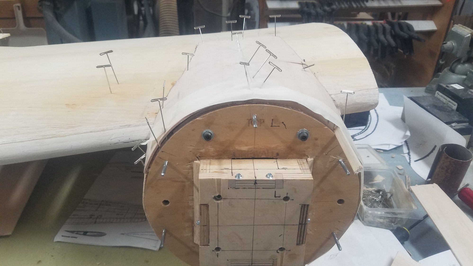
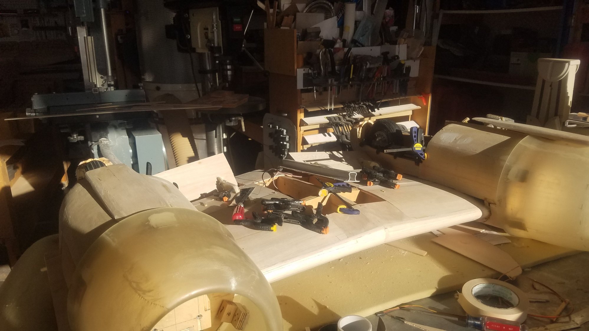
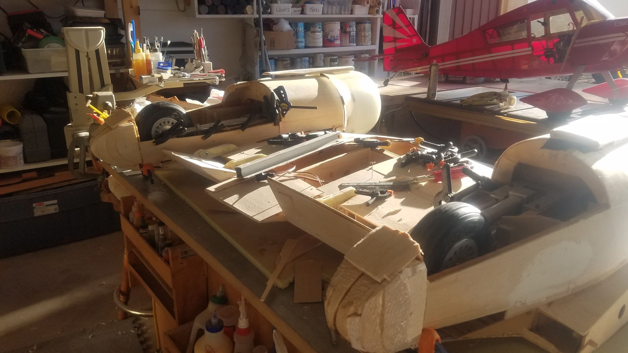
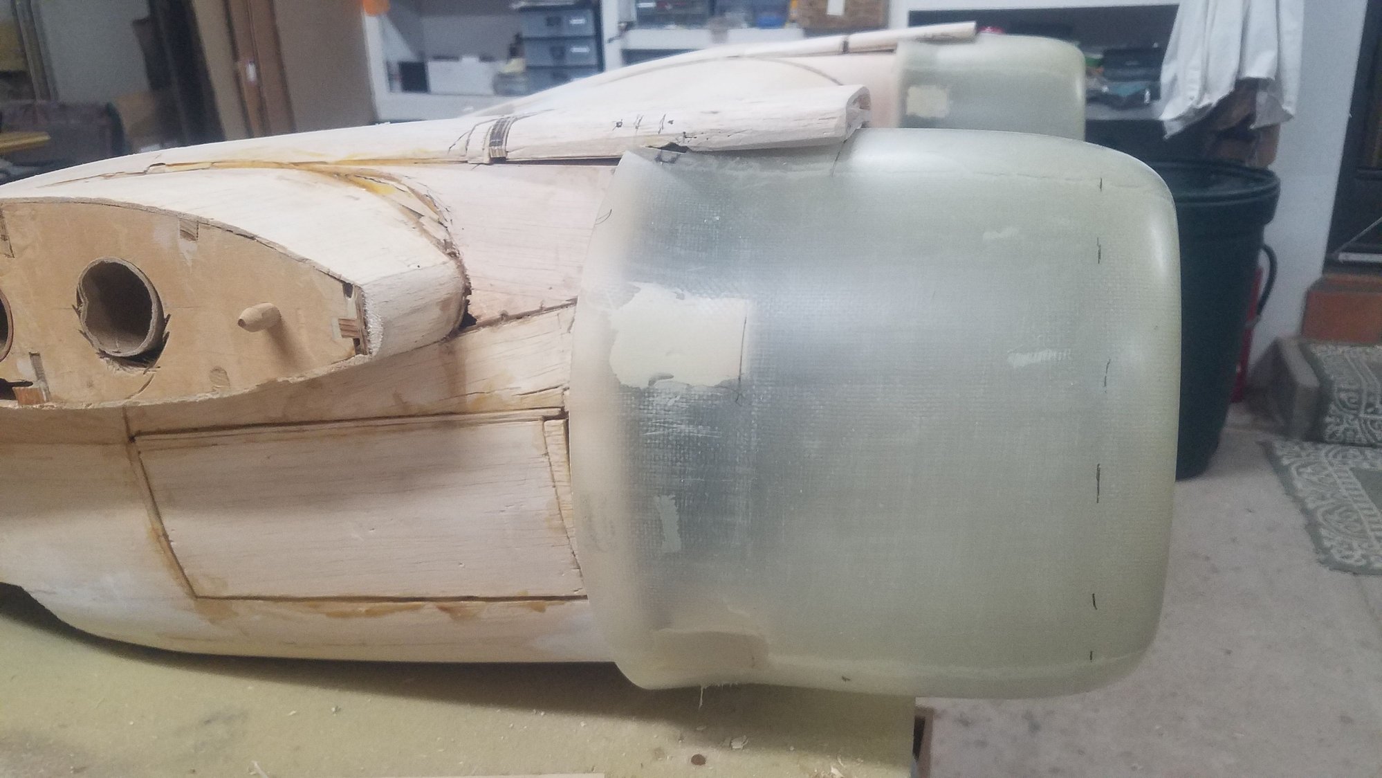
Stripped the first try at covering the nacelle and used this method.
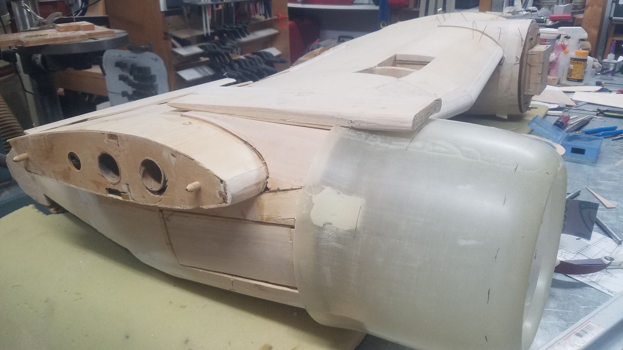
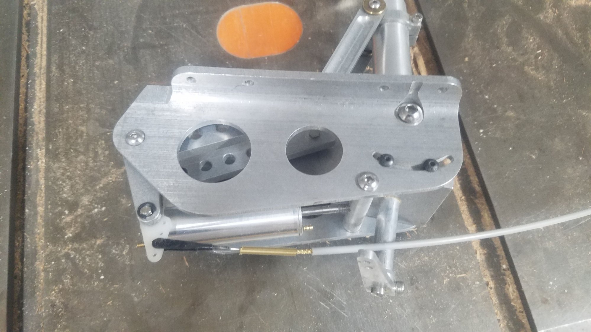
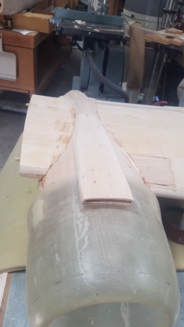
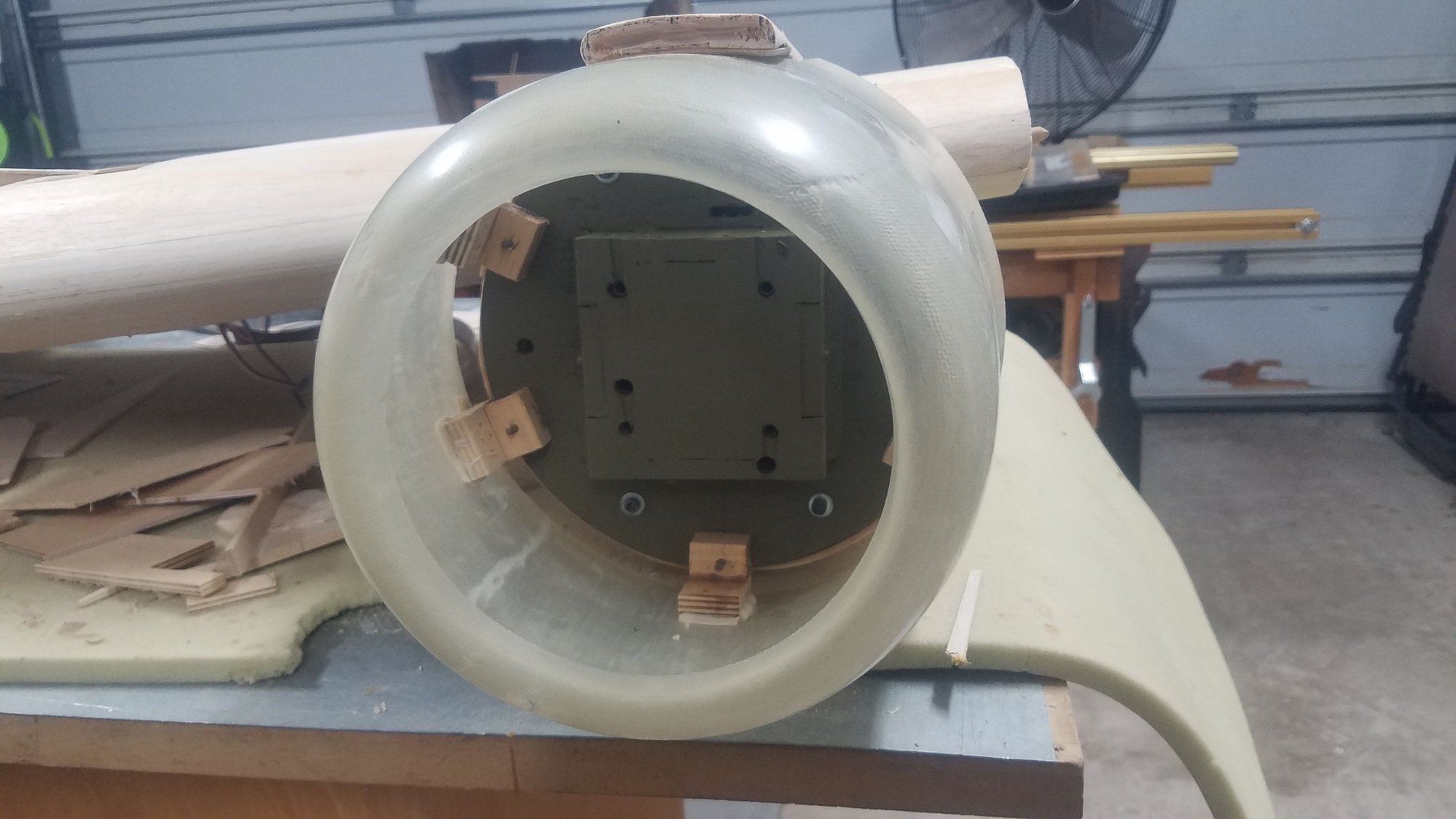
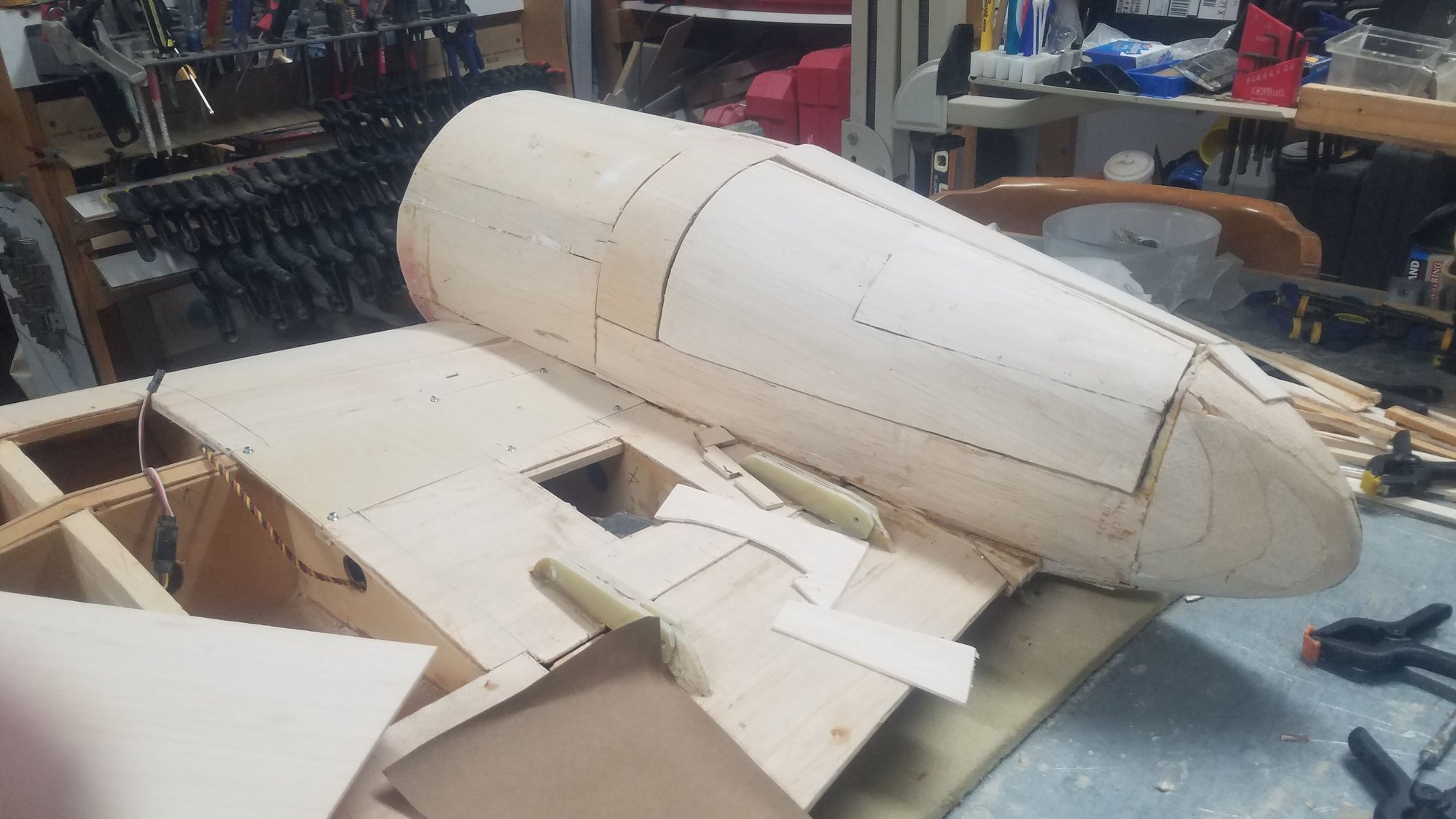
The air intake takes some fitting and refitting. Really not done fitting yet as the ridge down to the tail cone has to be figured out.
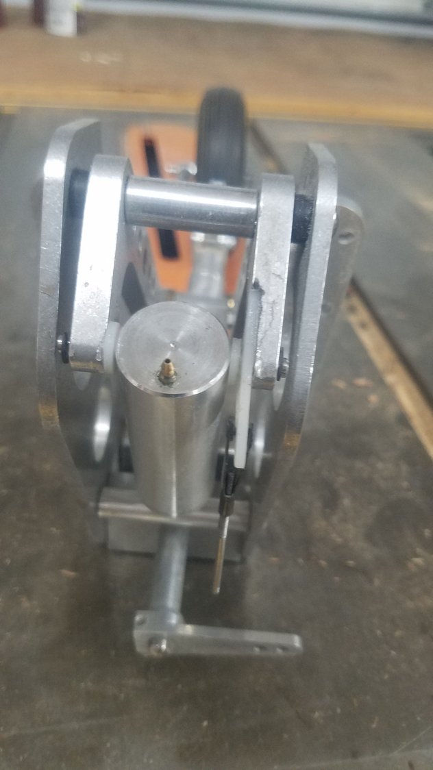
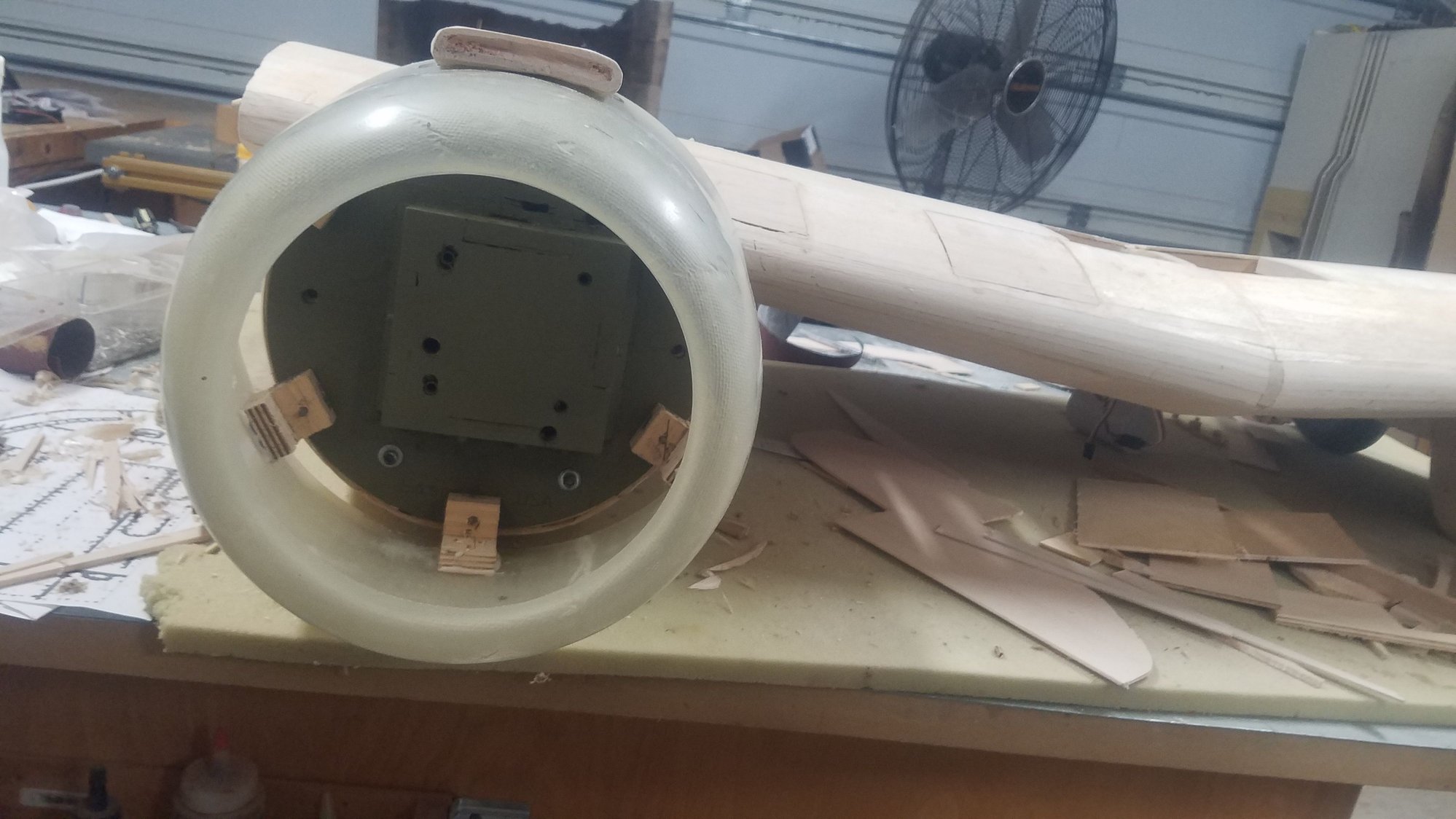
Air intake looks pretty good from the front. Needs to be hollowed out to finish it.
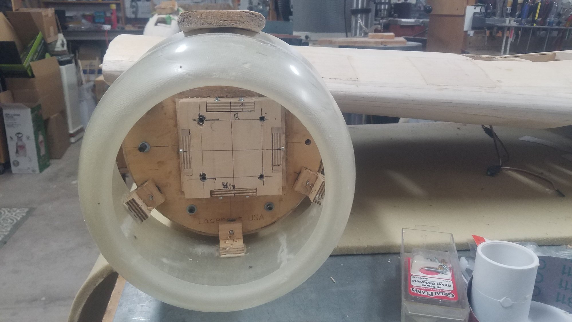
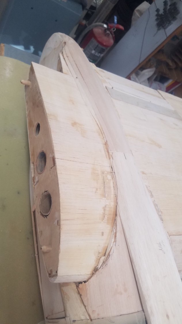
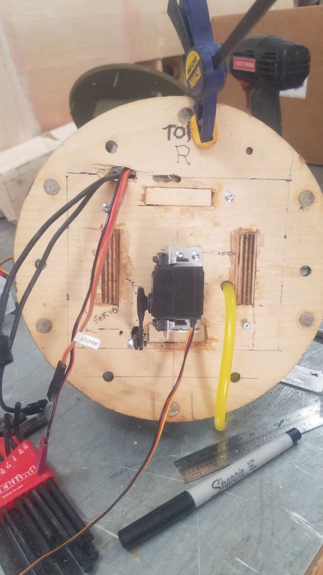
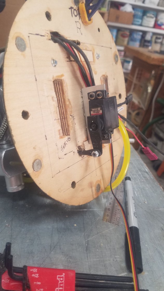
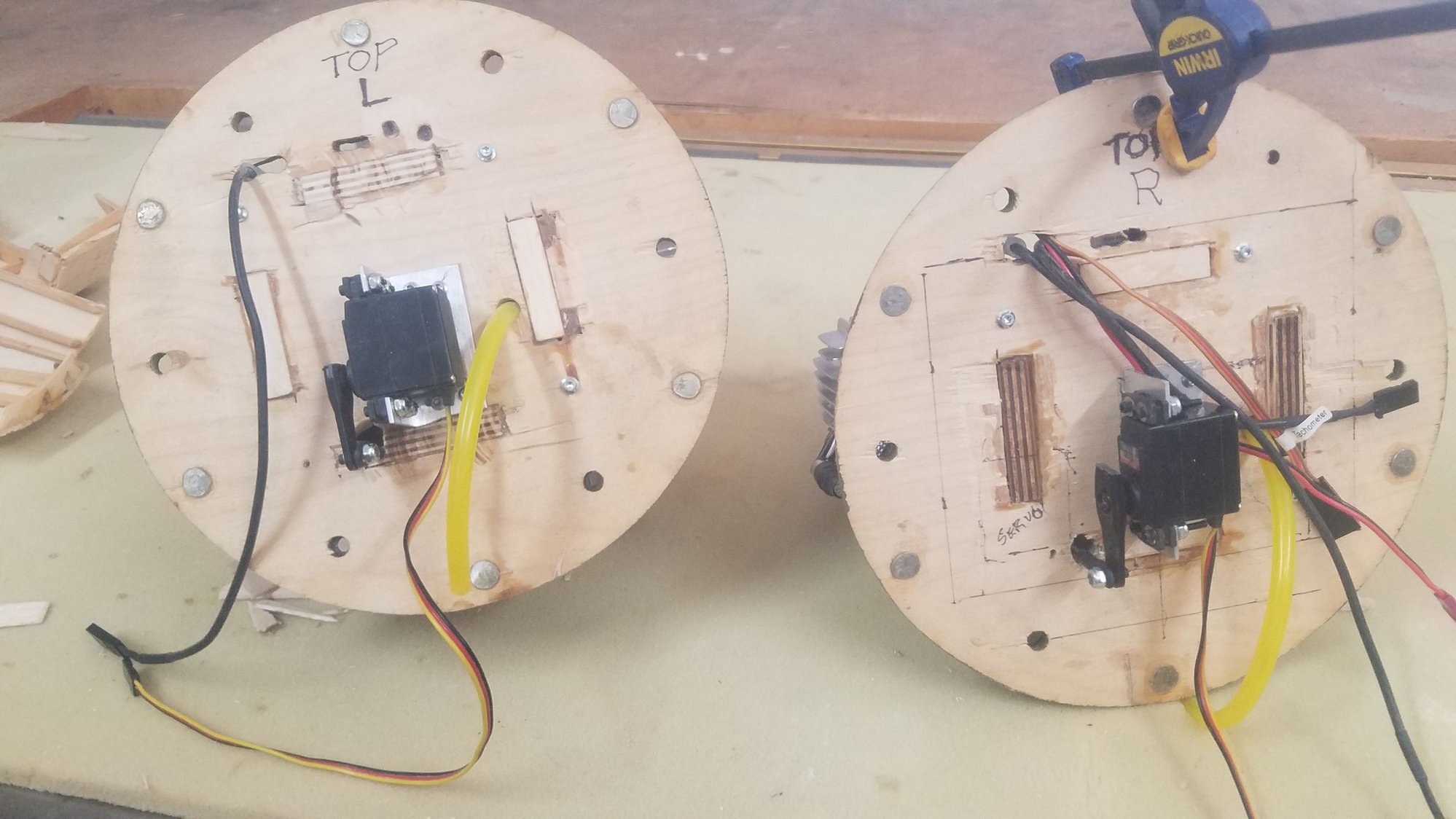
Attached a horn to an arm on the nose gear to operate the gear door that stays open when the gear is extended.
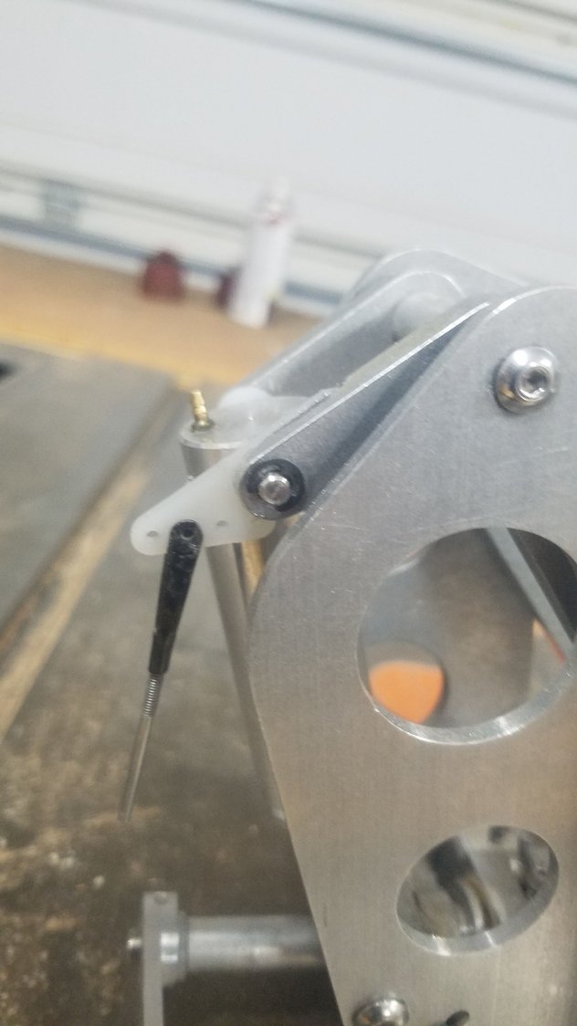
Filed out a slot to hold the horn and drilled a press fit hole for the pin. Will use aero poxy to hold in the horn in the slot.
Will take some trial and error to get the travel correct but the gear arc is 1.5 ins and the door swings at the far end 2.5 ins. The flex copper cable makes the curve to the door with no issues.
Stripped the first try at covering the nacelle and used this method.
The air intake takes some fitting and refitting. Really not done fitting yet as the ridge down to the tail cone has to be figured out.
Air intake looks pretty good from the front. Needs to be hollowed out to finish it.
Attached a horn to an arm on the nose gear to operate the gear door that stays open when the gear is extended.
Filed out a slot to hold the horn and drilled a press fit hole for the pin. Will use aero poxy to hold in the horn in the slot.
Will take some trial and error to get the travel correct but the gear arc is 1.5 ins and the door swings at the far end 2.5 ins. The flex copper cable makes the curve to the door with no issues.
09-24-2022, 05:34 PM
#135
Senior Member
Thread Starter
Weather got nice and wind quit blowing so it was time to take the new radio hook it up to some planes and go fly. Found the Elite does not bind to some of the older JR receivers but managed most of the new ones. Took some time off from the B-25 and worked on the other planes to update them and get them back in flying condition. Amazing what you can find in planes that haven't flow in some cases years. biggest issue was dead or faulty batteries. I decided to use the Elite for all my gas-powered planes and the 28X for all the electrics. As you cannot copy form the 28X to the Elite radio, so each plane has to be re-entered. Found that most settings had to be reversed to get the correct throws. No switch on the stick on the Elite so had to use the side slider switch to turn on the ignition. Also, the two-position switch on the back left is now momentary contact switch so a new gear switch had to be selected on the Elite. Here are the planes converted so far and some center section work on the B-25. Also installed a tool cabinet in the trailer which has been a nice addition. Great to be flying again.
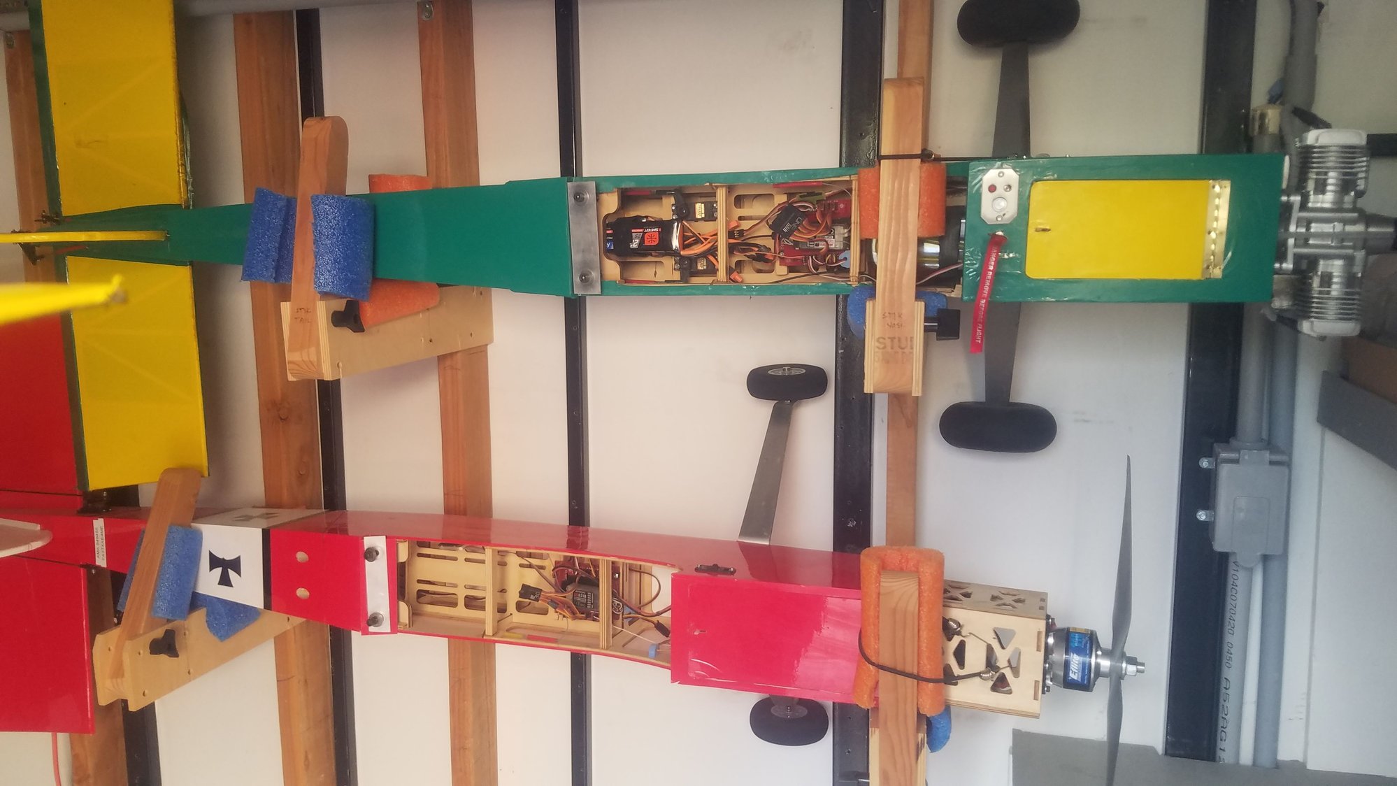
First converted to the Elite was my test bed Stik with a twin 40. The other Stik is an electric, both fly great. However, the gas Stick is much heavier and is a good practice for the war birds.
This little plane was actually given to me, and I converted it a 20-cc gas, again flies very well.
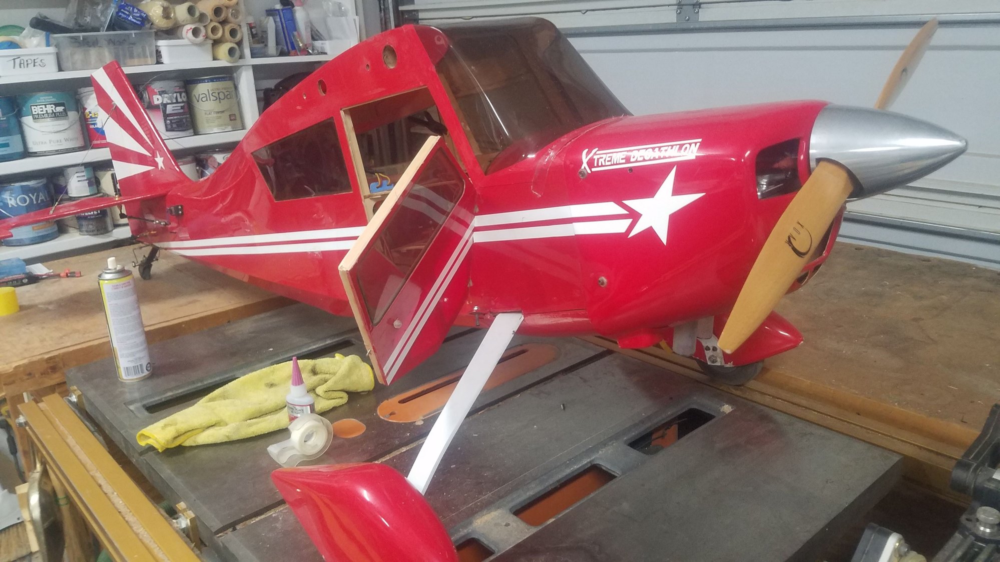
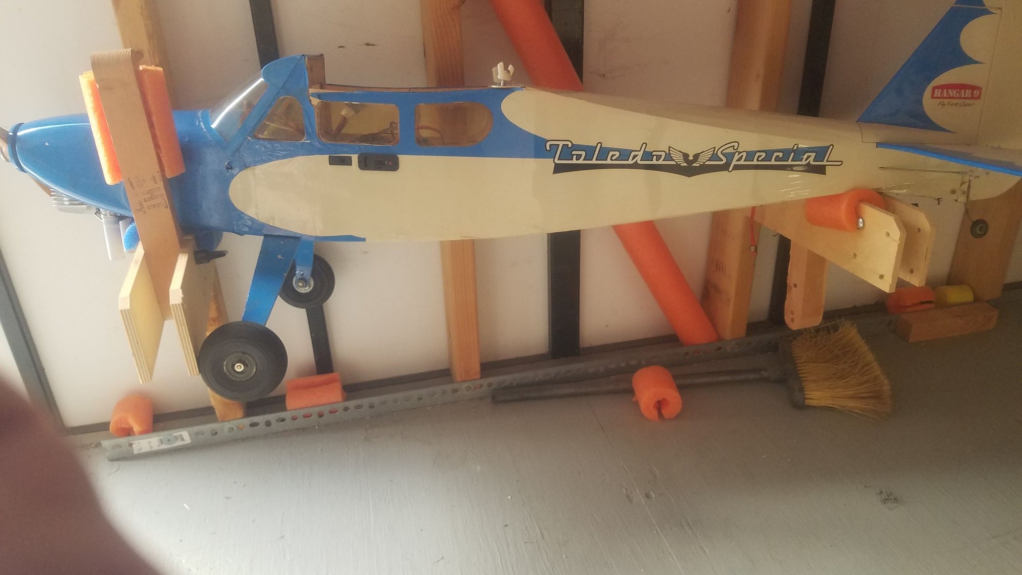
Decathlon has not flown for several years and the batteries which I left in it were destroyed. Looking forward to flying it, but it is a real hand full keeping it straight on takeoff. Hope to fly it next week.
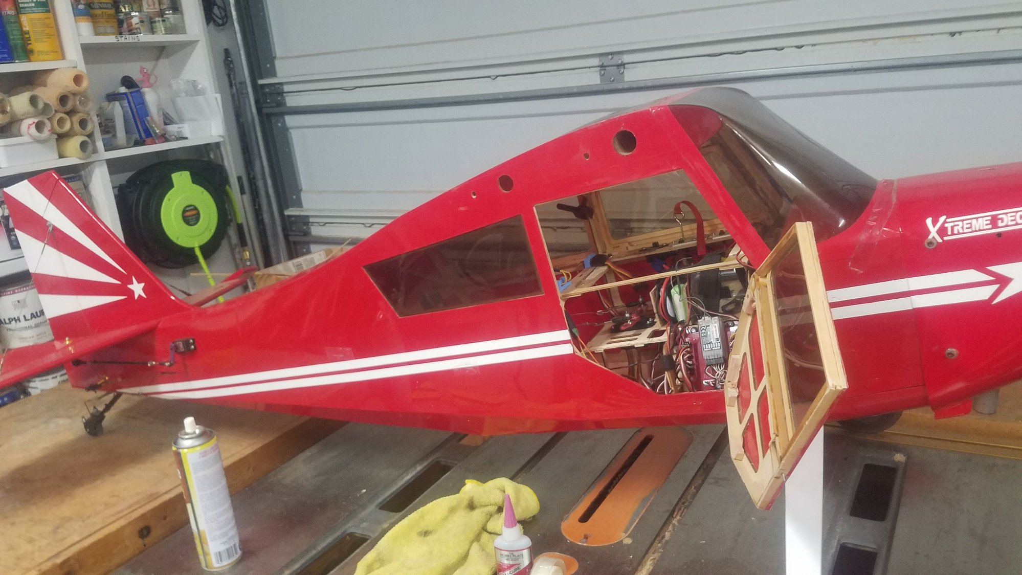
Changed batteries and added aux receiver and cleaned up some wiring.
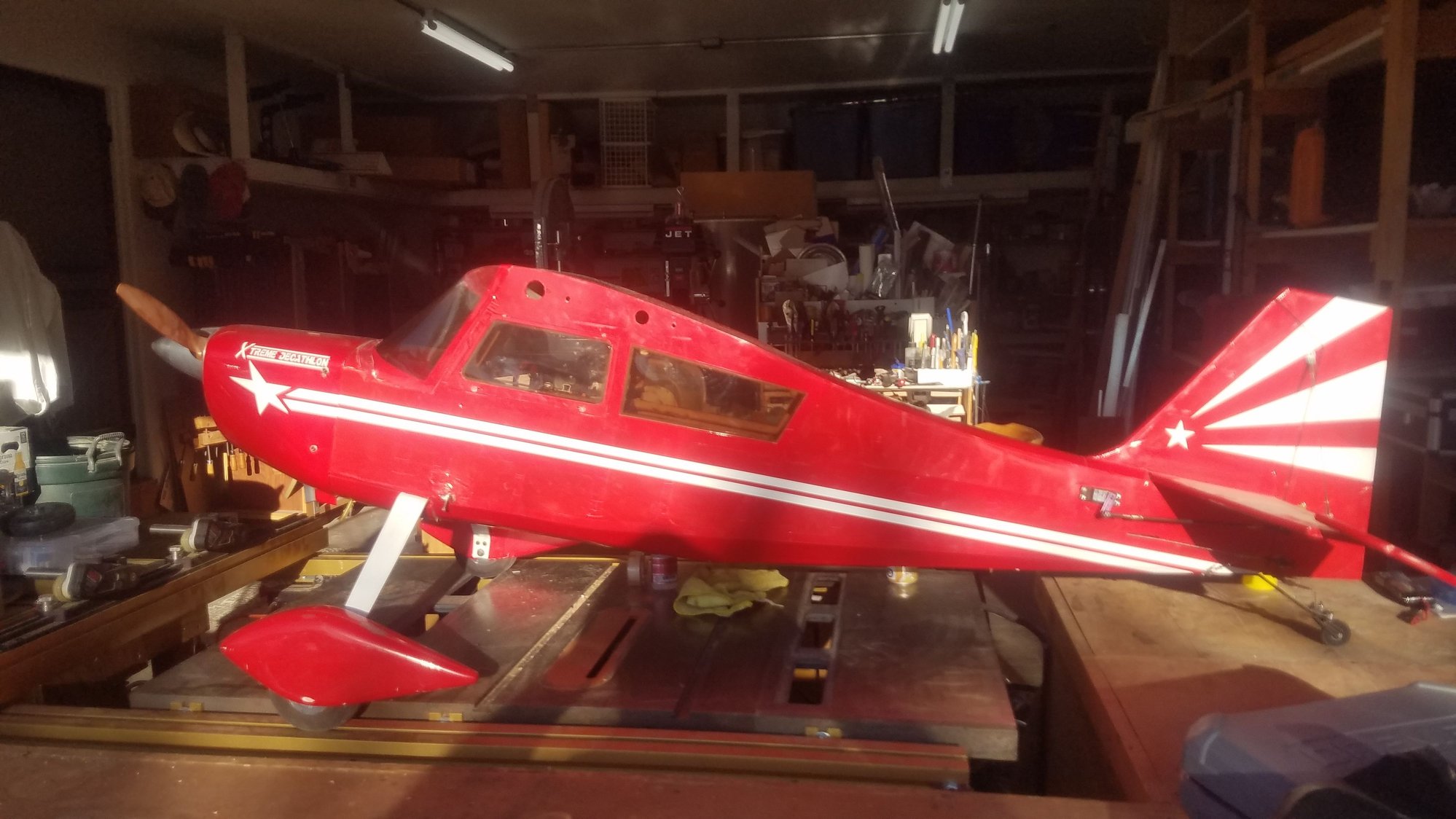
Hard to get off the ground but flies very well.
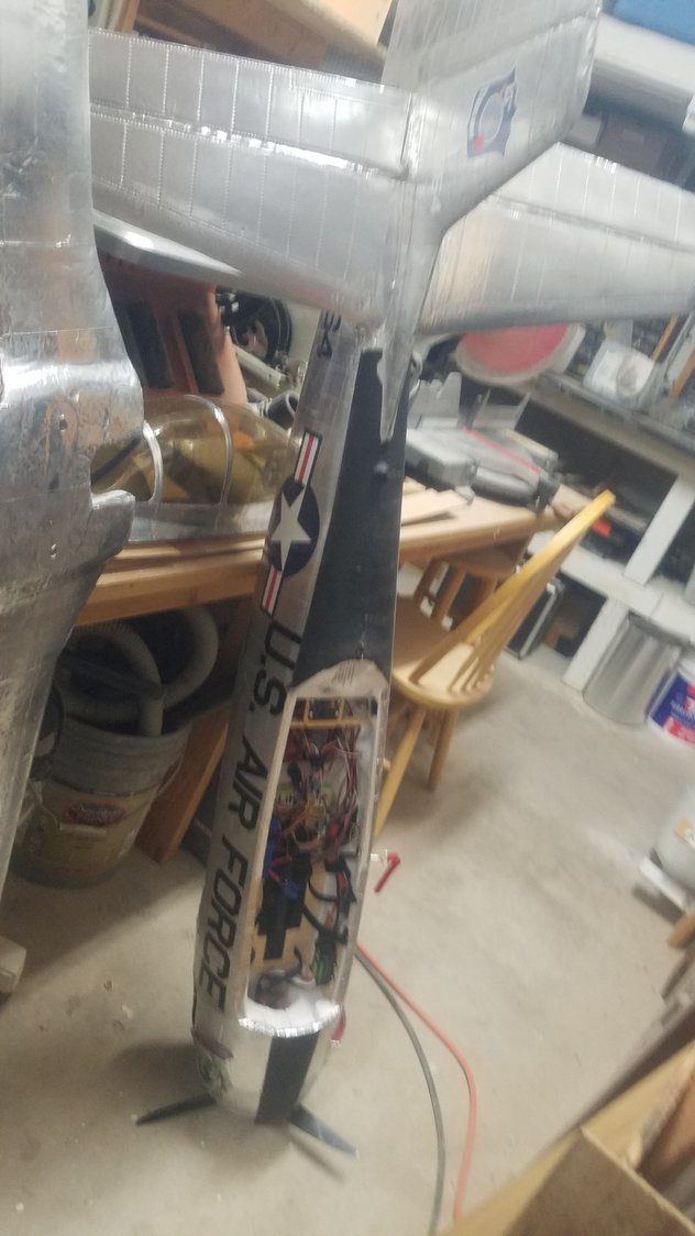
My converted Carbon Z T-28 has two bad aileron servos. This is a scale verion of the Air Force used as a fighter, it has alum skin, panel lines and rivets. It was a lot of work to convert.
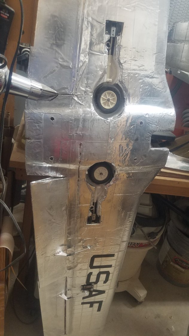
I had to cut out my alum covering to re-rout the wiring.
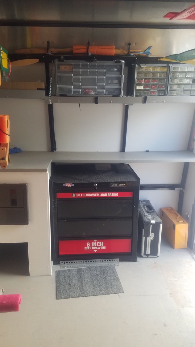
Installed a tool chest and it has been a great addition.
Back to the B-25. Center section skinning on the nacelles and top ridge added for air scoop.
Photos tomorrow on the ridge line as it is on the top of the center section nacelles.
First converted to the Elite was my test bed Stik with a twin 40. The other Stik is an electric, both fly great. However, the gas Stick is much heavier and is a good practice for the war birds.
This little plane was actually given to me, and I converted it a 20-cc gas, again flies very well.
Decathlon has not flown for several years and the batteries which I left in it were destroyed. Looking forward to flying it, but it is a real hand full keeping it straight on takeoff. Hope to fly it next week.
Changed batteries and added aux receiver and cleaned up some wiring.
Hard to get off the ground but flies very well.
My converted Carbon Z T-28 has two bad aileron servos. This is a scale verion of the Air Force used as a fighter, it has alum skin, panel lines and rivets. It was a lot of work to convert.
I had to cut out my alum covering to re-rout the wiring.
Installed a tool chest and it has been a great addition.
Back to the B-25. Center section skinning on the nacelles and top ridge added for air scoop.
Photos tomorrow on the ridge line as it is on the top of the center section nacelles.
09-25-2022, 08:25 PM
#137
Senior Member
Thread Starter
Continued work on the center section.
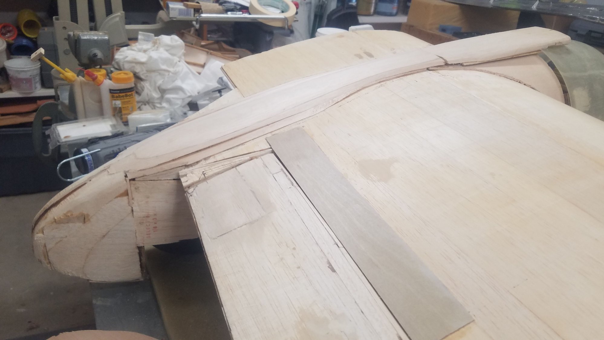
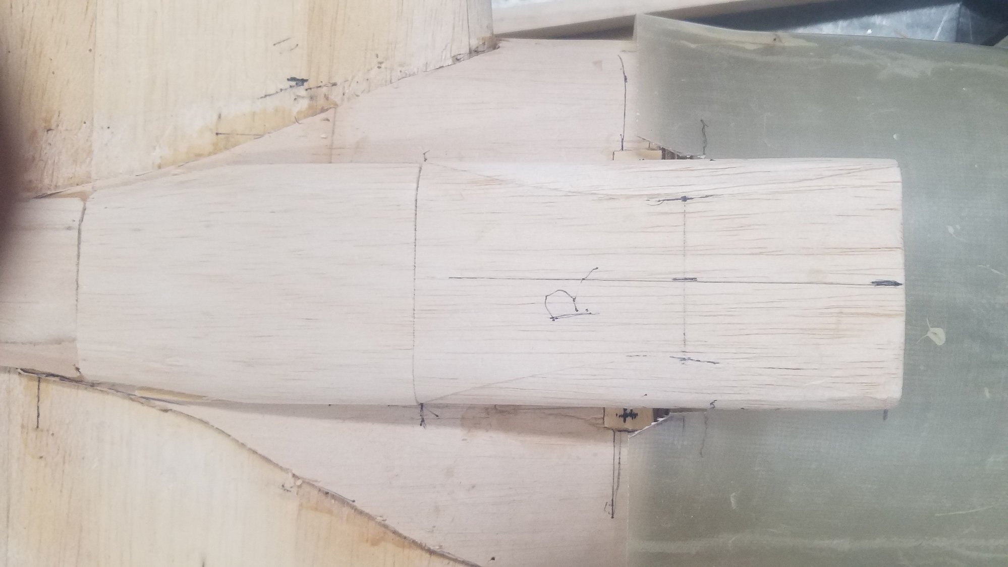
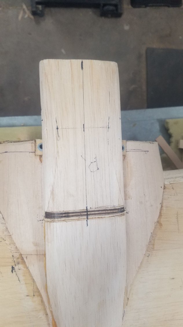
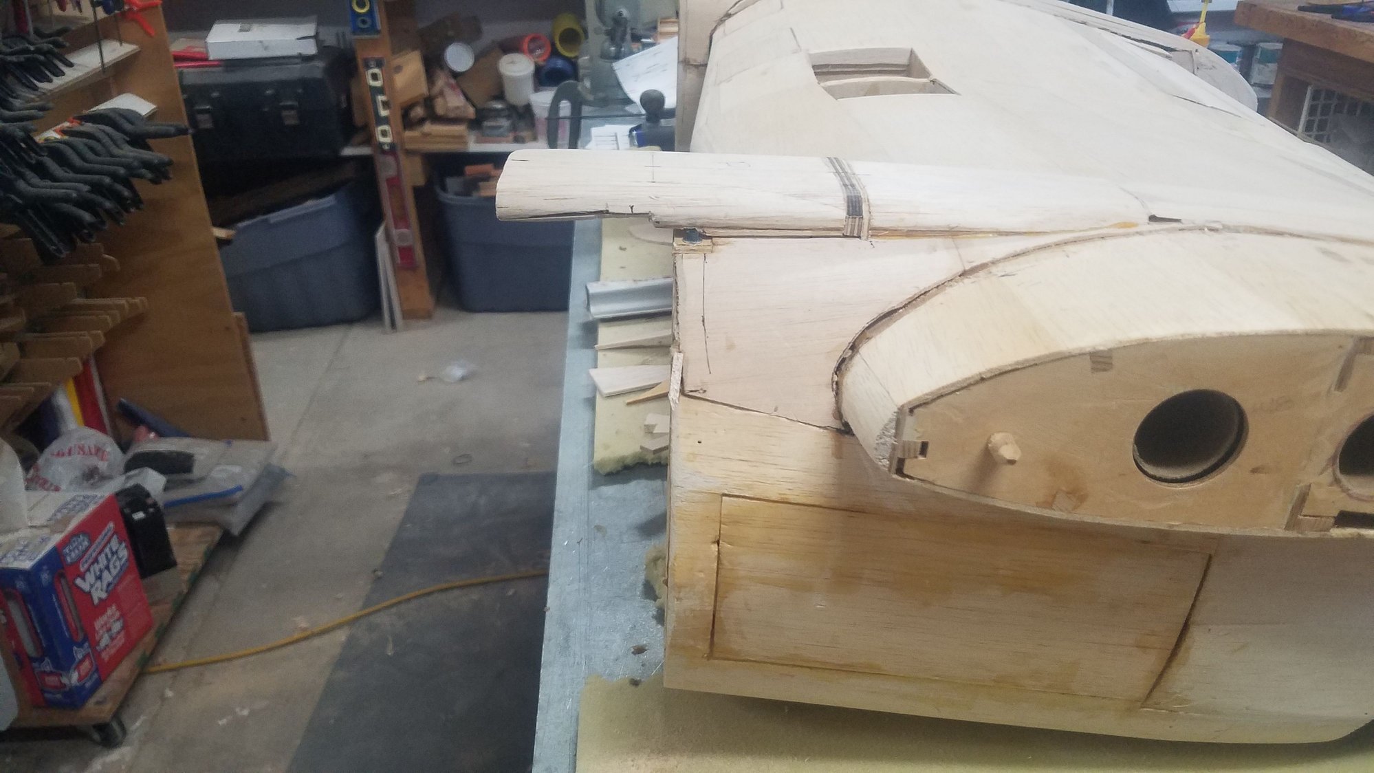
Right nacelle air scoop and ridge line.
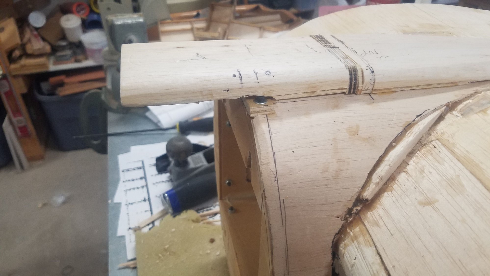
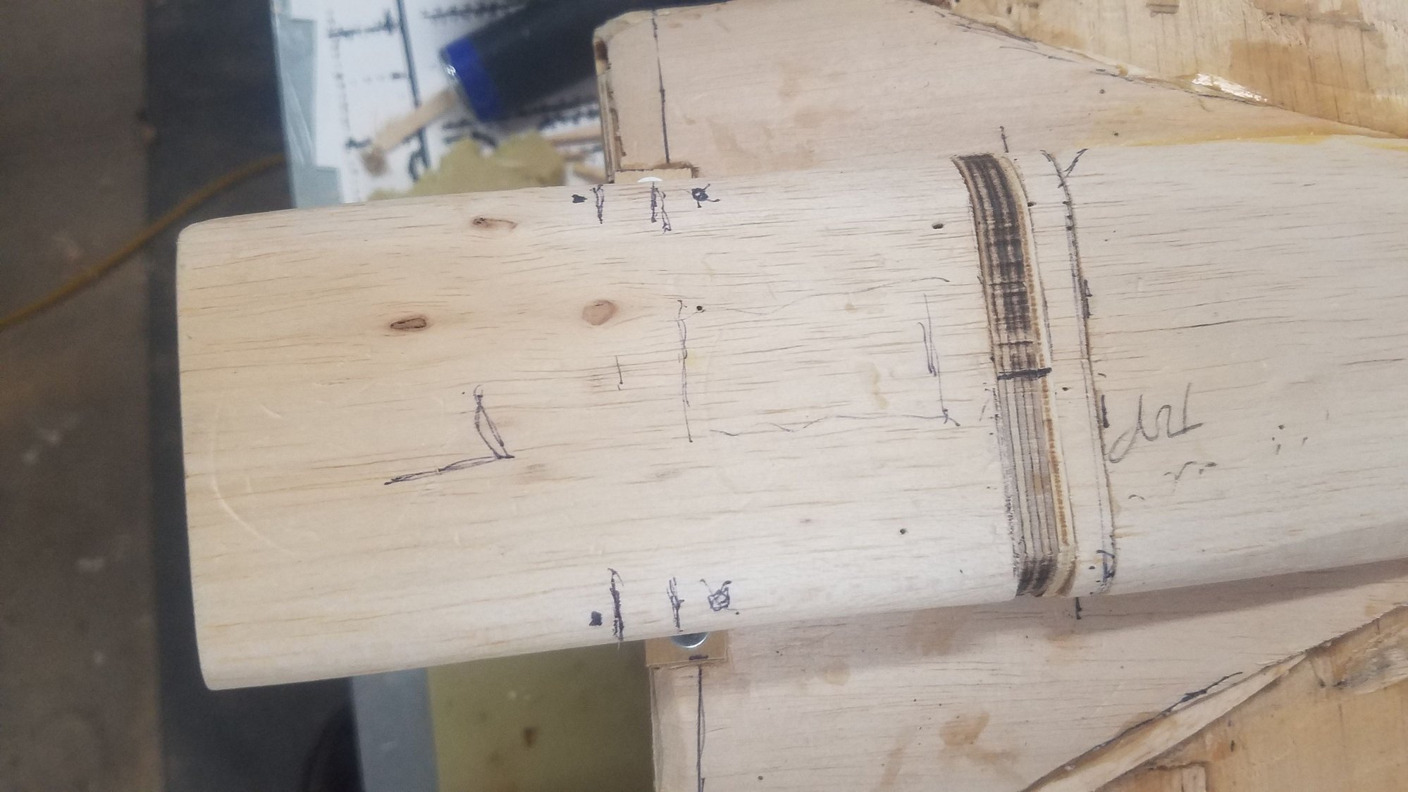
Roughing in air scoop ridge. Next will be the filler to flair it to the wing.
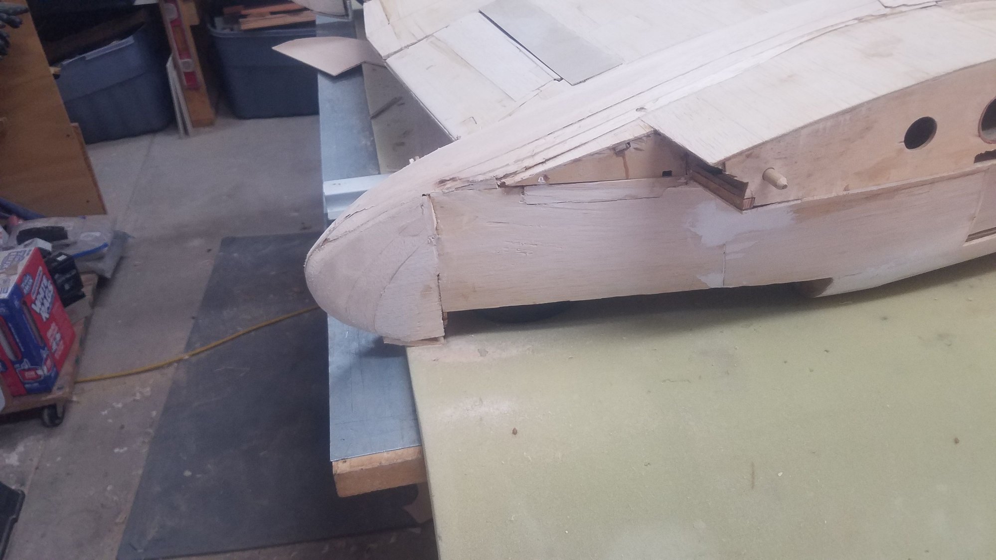
Roughing in the tail cones. This was a lot of shaping and sanding with more to go.
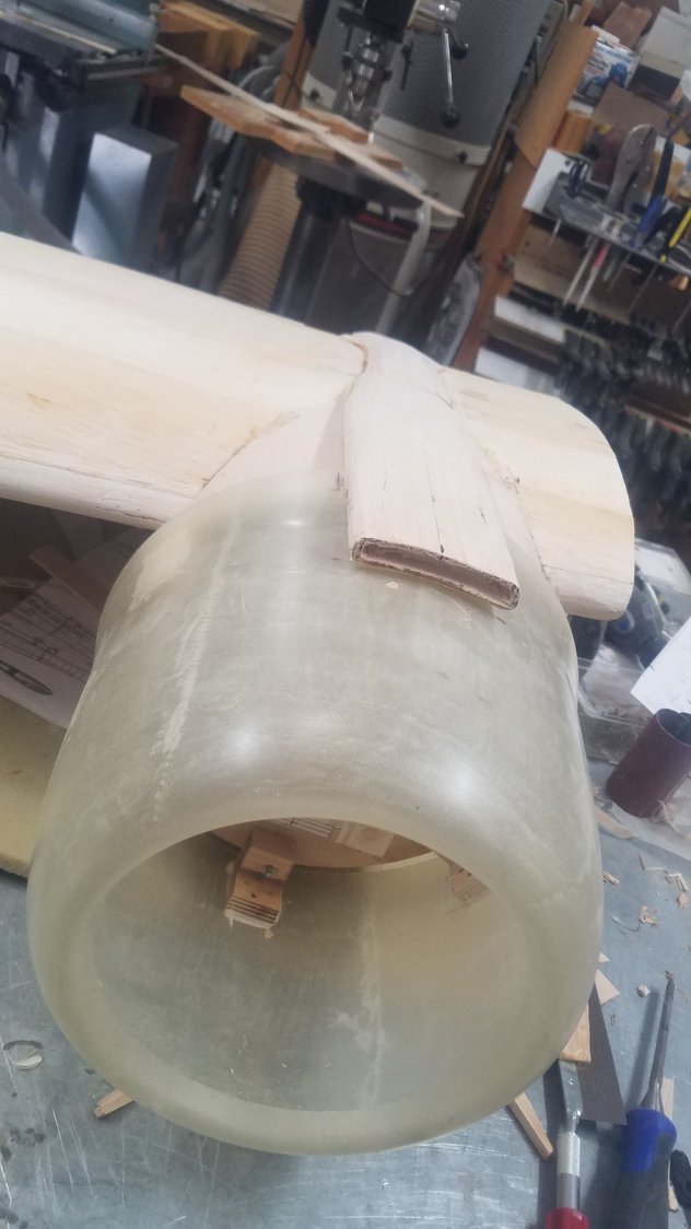
Left nacelle air scoop.
Roughing in the ridge line and tail cone on left nacelle. Will use filler to smooth the transition to the wing. More work to do on the flaps to make them scale on their transition to the nacelle.
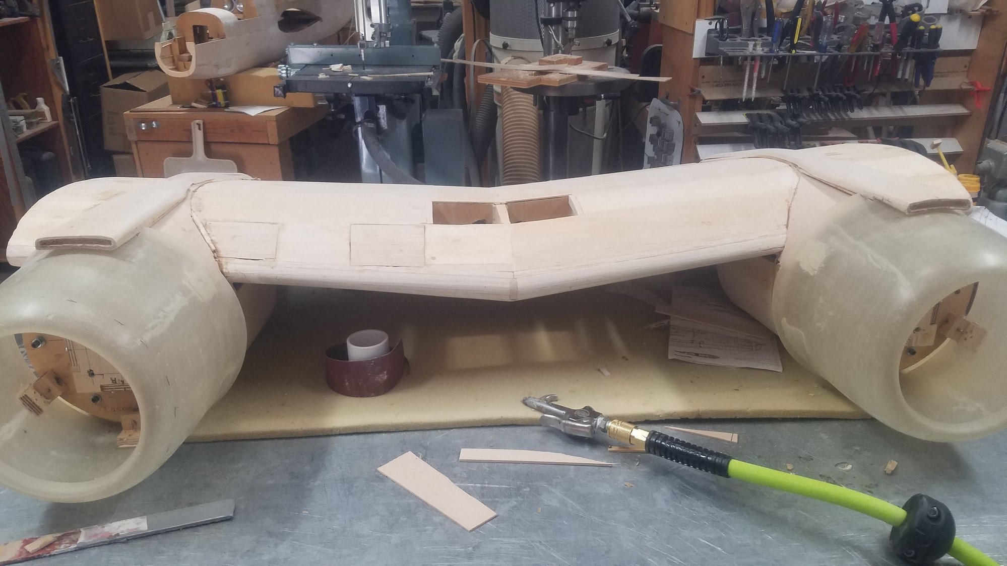
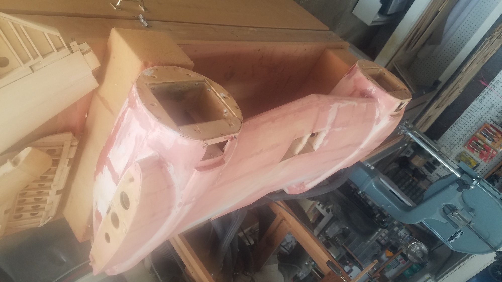
Center section frontal view. I am thinking of closing up the side hatch which was cut in when I was considering electric power for access to the required massive battery packs. If I do this, to get to the ignition battery, ignition unit, throttle servo and fuel tank in each nacelle the removable fire wall would be taken off the front for access.
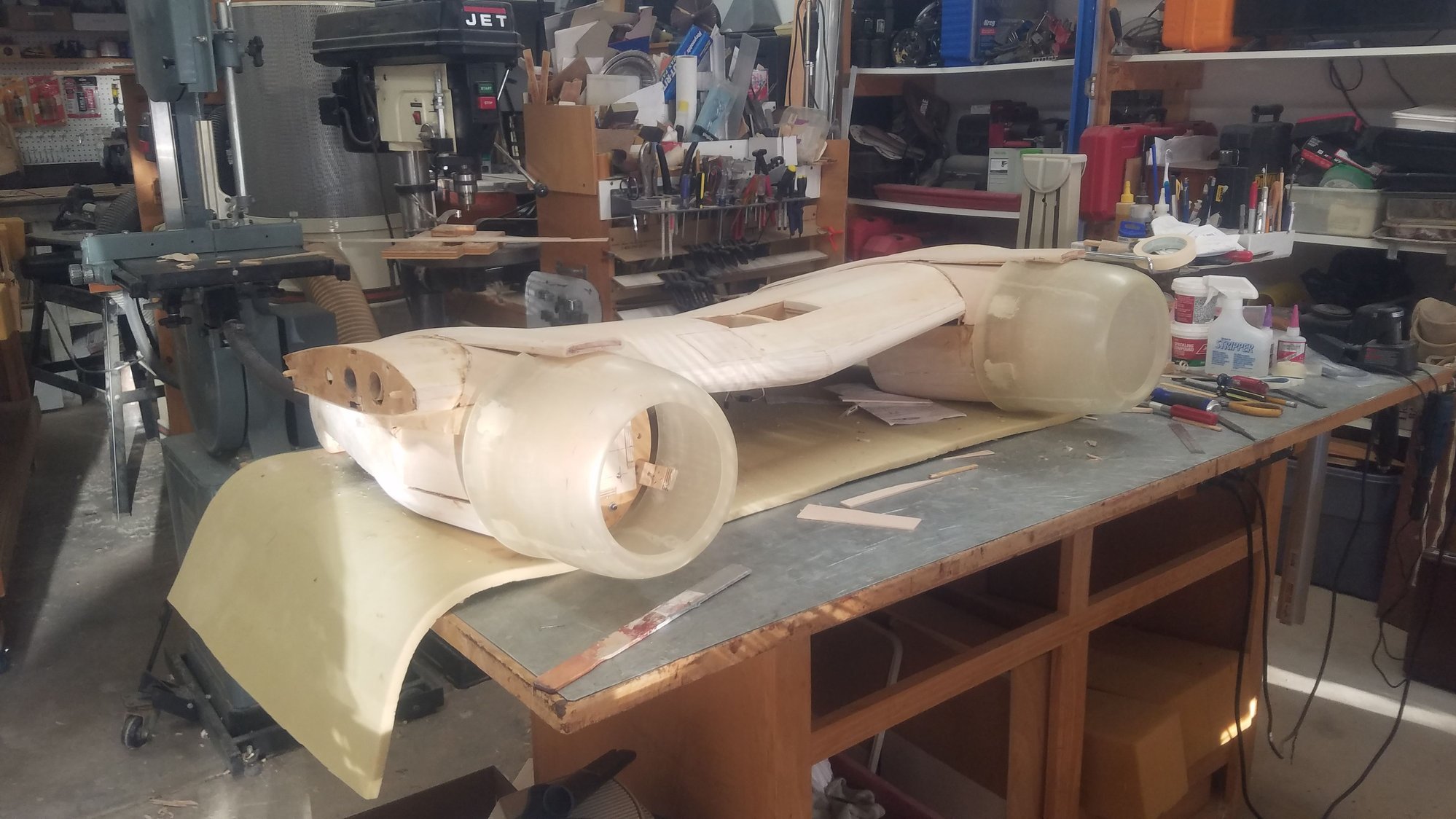
Thinking about making the air scoops removable with switches, battery charge connections and re-fuel port on the top of the nacelle rather than on the side.
Right nacelle air scoop and ridge line.
Roughing in air scoop ridge. Next will be the filler to flair it to the wing.
Roughing in the tail cones. This was a lot of shaping and sanding with more to go.
Left nacelle air scoop.
Roughing in the ridge line and tail cone on left nacelle. Will use filler to smooth the transition to the wing. More work to do on the flaps to make them scale on their transition to the nacelle.
Center section frontal view. I am thinking of closing up the side hatch which was cut in when I was considering electric power for access to the required massive battery packs. If I do this, to get to the ignition battery, ignition unit, throttle servo and fuel tank in each nacelle the removable fire wall would be taken off the front for access.
Thinking about making the air scoops removable with switches, battery charge connections and re-fuel port on the top of the nacelle rather than on the side.
09-26-2022, 07:06 PM
#138
Senior Member
Thread Starter
Went to use the wood filler and found it unusable due to too much time setting on the shelf, reordered and should have it in a few days.
Decided to make the air scoops removable and I spent some time figuring it out how to do that without showing the hold down bolts. More work needed to complete the scoops later in the week as I can't get back to the B-25 for several days.
Waited too long to use the filler. The hardener was solid, and the filler was too thick to flow - reordered.
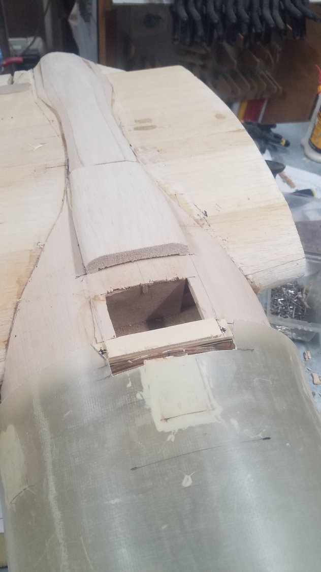
Opened area under the scoop for fuel, battery leads and possibly a switch. Cut out front bulkhead area so that a hold down strip can be bolted down hidden by the cowl flap which is slightly opened to just expose the bolts.
Blind nuts and bolts not yet installed in this view. If you look closely, you can just see the cowl is opened slightly to get to the hold down bolt location, one on each side of the scoop.
Back of the removeable scoop will be pinned into the rear member to hold it down and centered. Making the scoop removable will also help in that it cannot be broken off in the construction phase if the center section were tipped forward on to the firewall by accident.
Decided to make the air scoops removable and I spent some time figuring it out how to do that without showing the hold down bolts. More work needed to complete the scoops later in the week as I can't get back to the B-25 for several days.
Waited too long to use the filler. The hardener was solid, and the filler was too thick to flow - reordered.
Opened area under the scoop for fuel, battery leads and possibly a switch. Cut out front bulkhead area so that a hold down strip can be bolted down hidden by the cowl flap which is slightly opened to just expose the bolts.
Blind nuts and bolts not yet installed in this view. If you look closely, you can just see the cowl is opened slightly to get to the hold down bolt location, one on each side of the scoop.
Back of the removeable scoop will be pinned into the rear member to hold it down and centered. Making the scoop removable will also help in that it cannot be broken off in the construction phase if the center section were tipped forward on to the firewall by accident.
Last edited by rossmick; 09-26-2022 at 07:10 PM.
The following users liked this post:
penper (09-27-2022)
09-30-2022, 07:02 PM
#139
Senior Member
Thread Starter
Got some time to do some more work. Most of the week broken up with other duties. Closed the hatch openings in the nacelles, Created the removeable scoops for ignition battery location. Drilled out firewall for fuel line, throttle linkage, and ignition lead. Problem now with mufflers.
Closed up the right access door area that I had cut in for the large LIPO batteries when I considered electric power. Was able to glue three sides to get the strength back for the nacelle required for the gas power.
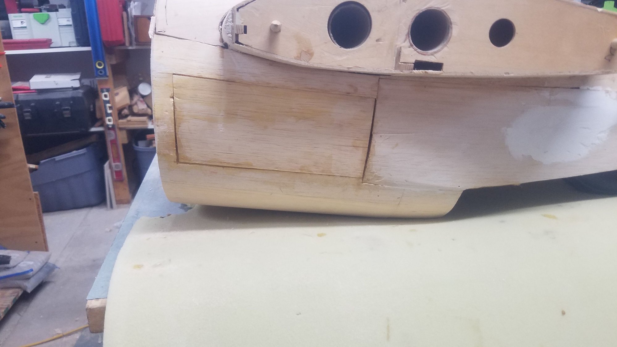
Right outside door glued back in, filler required.
Left nacelle access door closed. Best guess idea on location of the fuel tank at this time.
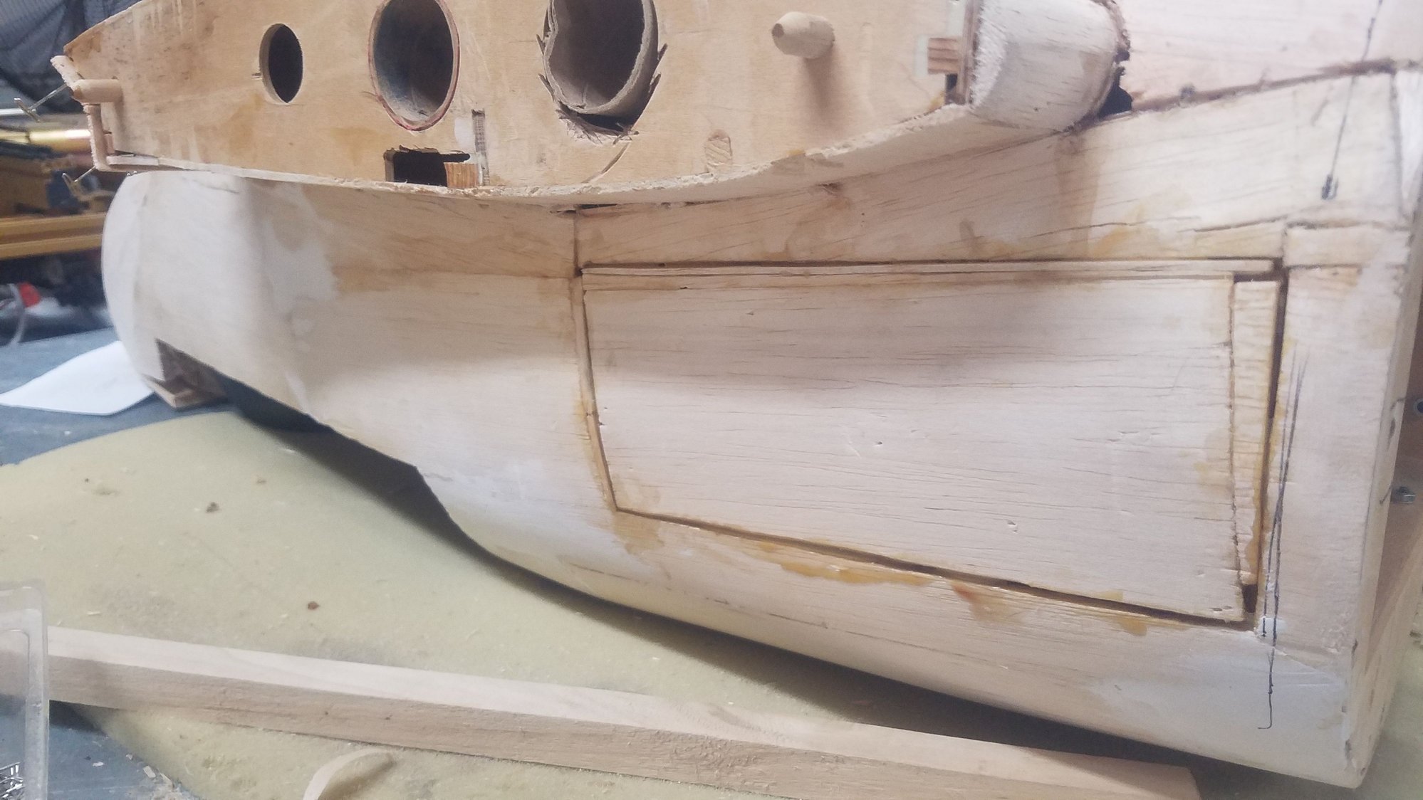
Left nacelle door glued back in. Will take a lot of filler to blend back to the nacelle. Feeling much better about the strength of the nacelles.
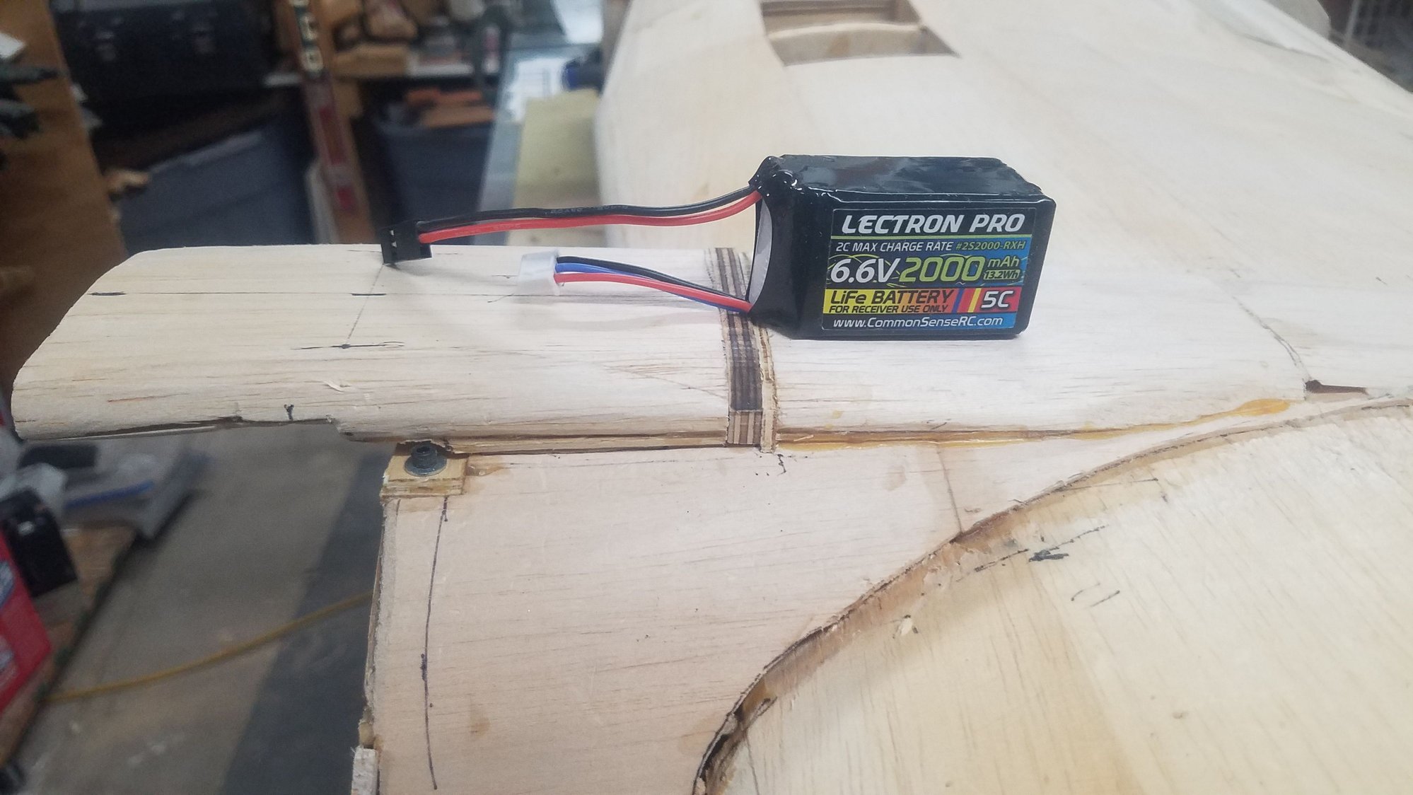
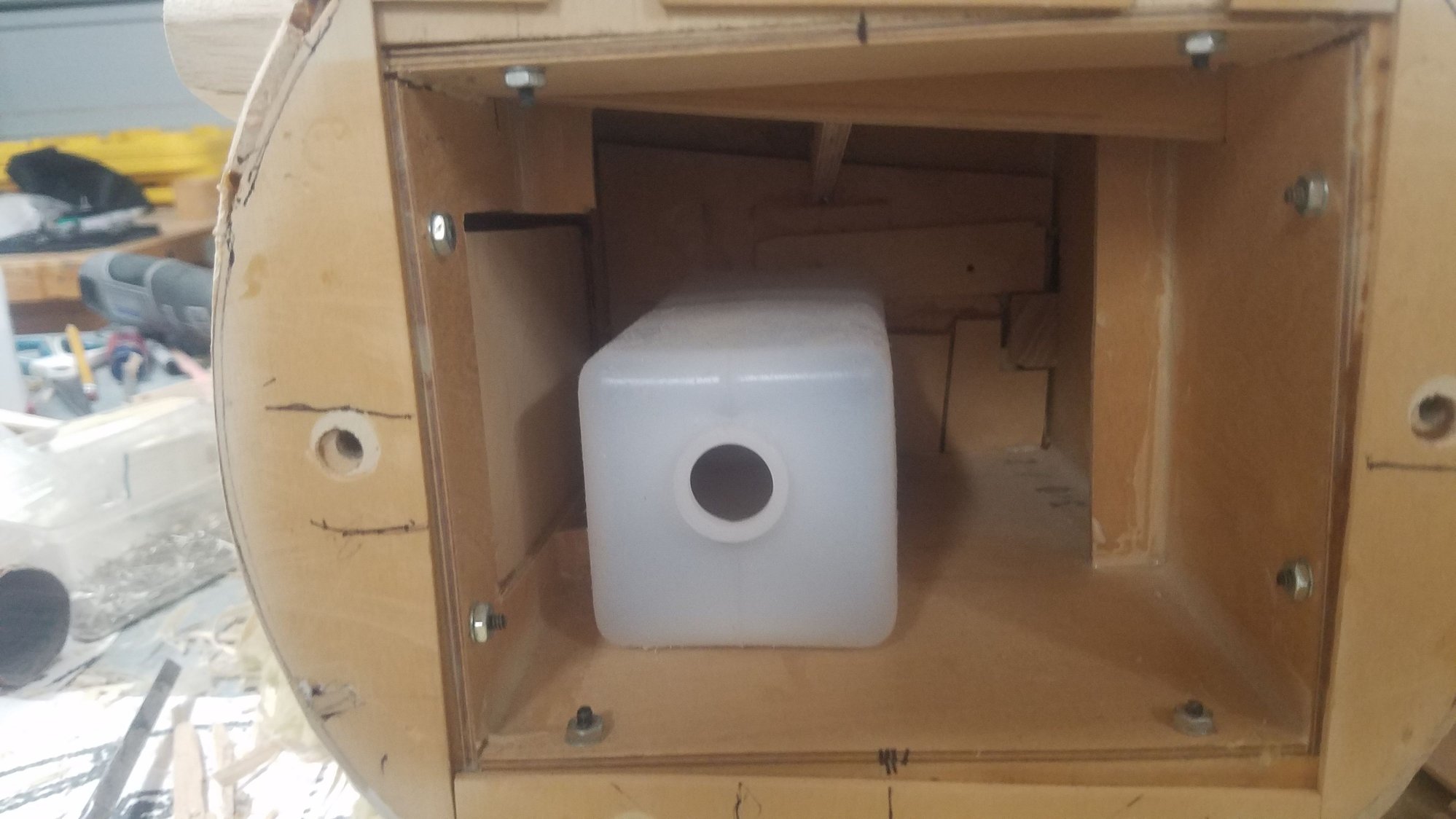
Photo of the battery that I will use for the ignition. I want the battery as close as possible to the control unit which will be mounted next to the fuel tank. Idea here is to use the removeable scoops to get to the battery for charging. My charger requires the cell lead connected for cell balance. Neat size for 2000 mAh.
Battey in temporary unsupported location under the scoop.
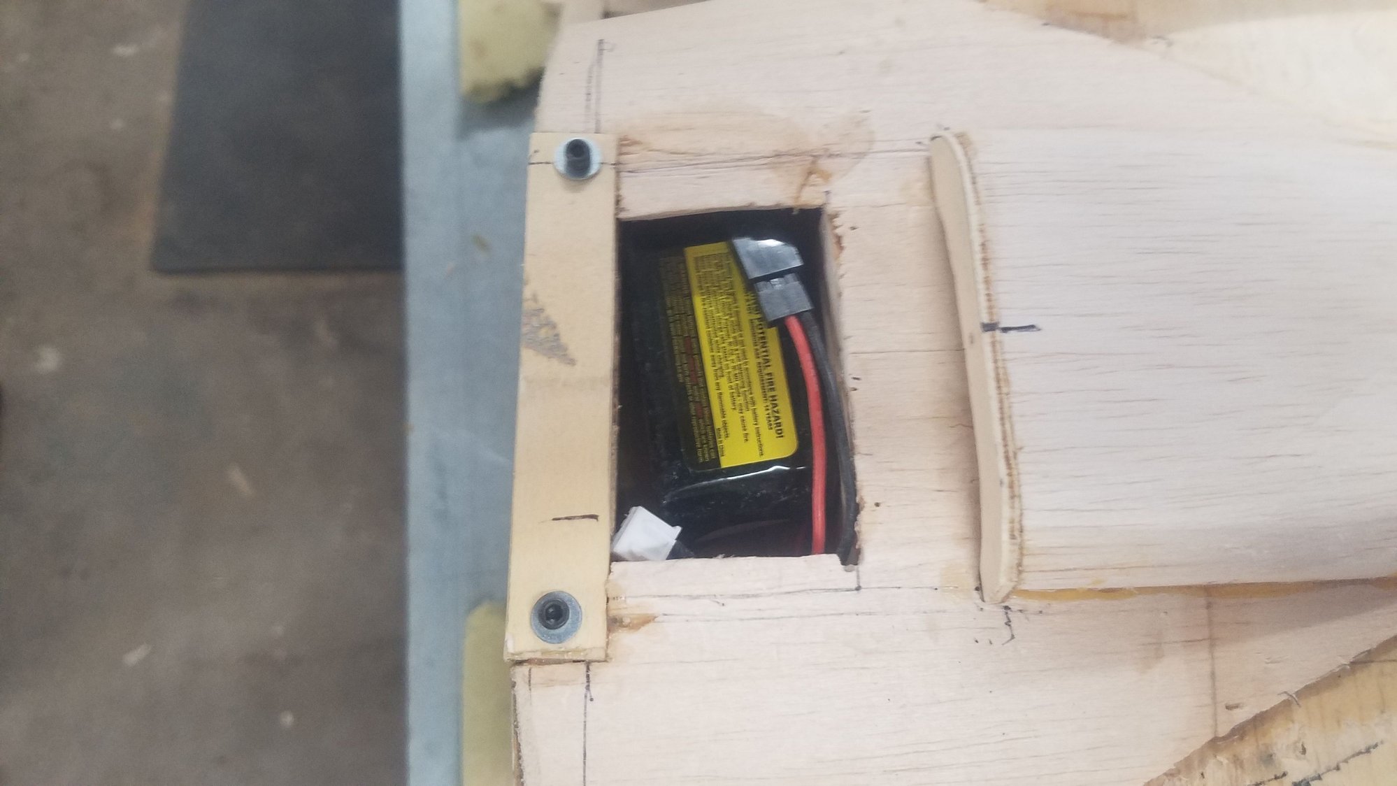
Removeable section of the scoop. Pin at rear will hold it down at the back.
Removeable section in place but not glued to bolt down plate in the front.
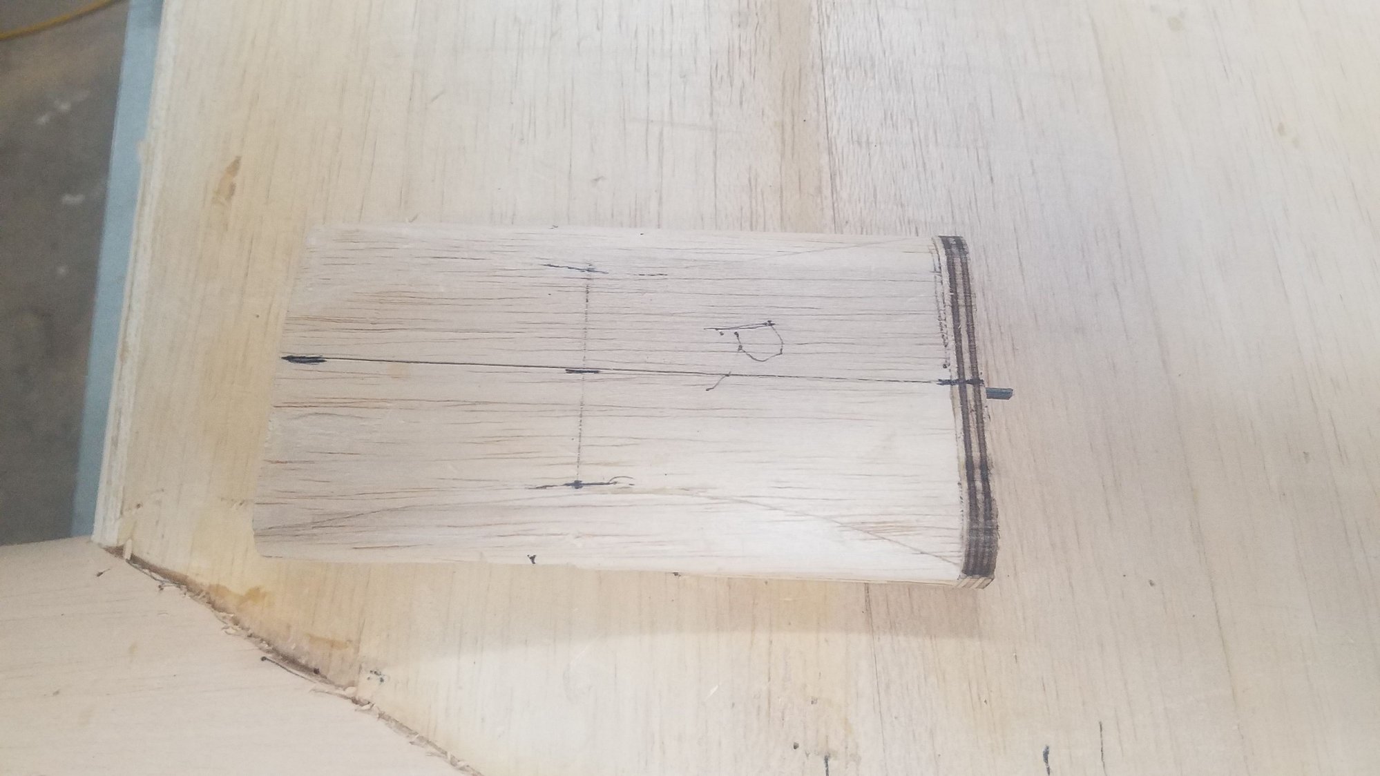
Just a right-side view of the scoop.
Left-side scoop. Note the ply rear member which hold the rear pin.
Left scoop in place showing the mistake I made when I cut in the ply section cutout twice. I glued the piece back in to get the correct length.
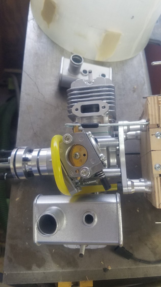
I drilled out the firewall for throttle linkage, ignition wire, and fuel line. Muffler removed to get to throttle linkage. Looks like a special muffler will have to be ordered if possible.
Problem with this engine is that when the muffler has the stacks mounted to the rear you cannot get to the mixture needle values. They recommend just flipping the mufflers around. I don't like the exhaust stacks to the front, so checking if custom mufflers can be manufactured. What the heck - it's just more money.
Closed up the right access door area that I had cut in for the large LIPO batteries when I considered electric power. Was able to glue three sides to get the strength back for the nacelle required for the gas power.
Right outside door glued back in, filler required.
Left nacelle access door closed. Best guess idea on location of the fuel tank at this time.
Left nacelle door glued back in. Will take a lot of filler to blend back to the nacelle. Feeling much better about the strength of the nacelles.
Photo of the battery that I will use for the ignition. I want the battery as close as possible to the control unit which will be mounted next to the fuel tank. Idea here is to use the removeable scoops to get to the battery for charging. My charger requires the cell lead connected for cell balance. Neat size for 2000 mAh.
Battey in temporary unsupported location under the scoop.
Removeable section of the scoop. Pin at rear will hold it down at the back.
Removeable section in place but not glued to bolt down plate in the front.
Just a right-side view of the scoop.
Left-side scoop. Note the ply rear member which hold the rear pin.
Left scoop in place showing the mistake I made when I cut in the ply section cutout twice. I glued the piece back in to get the correct length.
I drilled out the firewall for throttle linkage, ignition wire, and fuel line. Muffler removed to get to throttle linkage. Looks like a special muffler will have to be ordered if possible.
Problem with this engine is that when the muffler has the stacks mounted to the rear you cannot get to the mixture needle values. They recommend just flipping the mufflers around. I don't like the exhaust stacks to the front, so checking if custom mufflers can be manufactured. What the heck - it's just more money.
10-01-2022, 07:22 PM
#140
Senior Member
Thread Starter
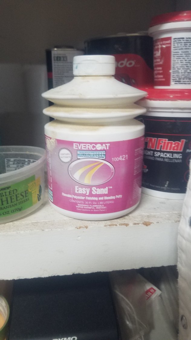
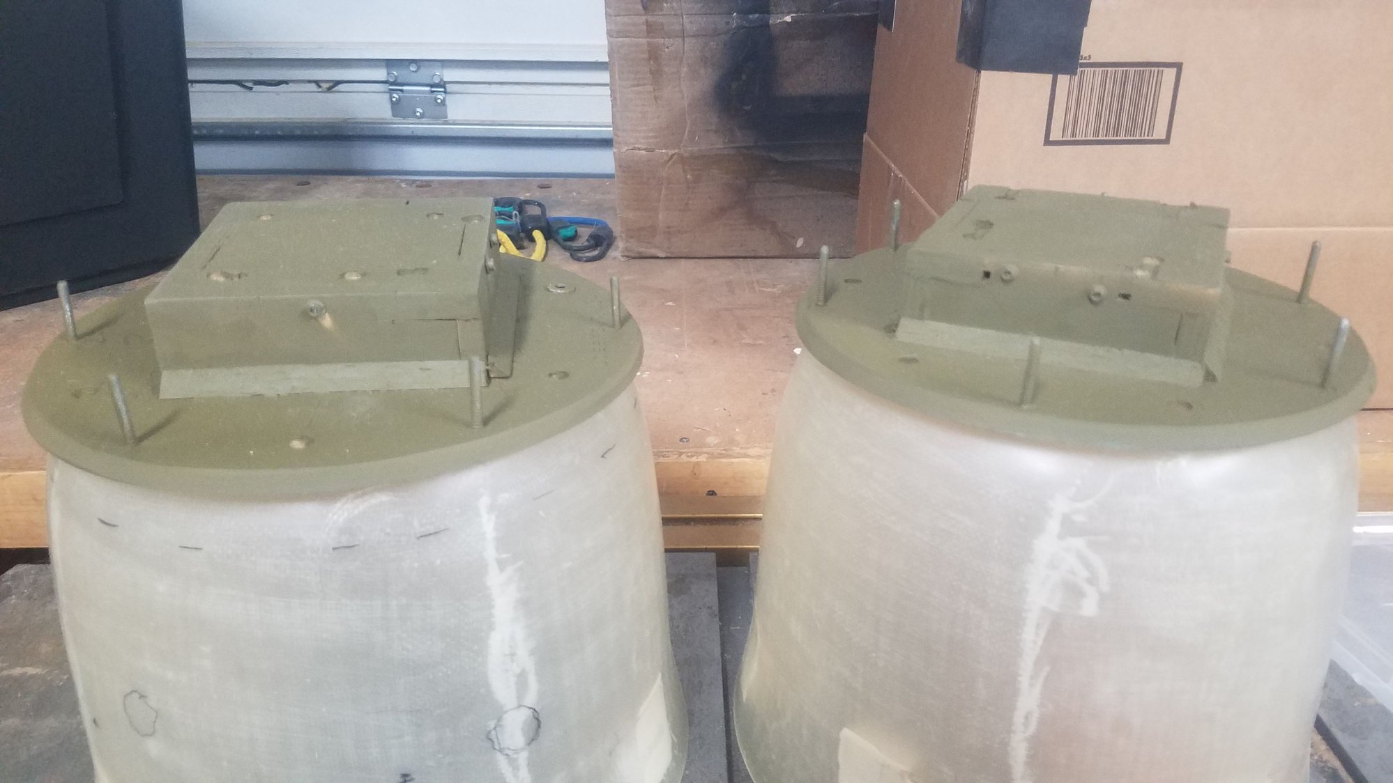
Spent most of the day laying out and attaching the engines to the firewalls. I solved the muffler issue by swapping left to right and then using the left from the other engine. Ordered another set of mufflers for the other engine. Throttle arm changed to the longer version. I used a #2 screw to thread the hole in the arm. I also used a nut with locktite to attach the swivel linkage. Used threaded rod to reach the servo which will be mounted on the back of the firewall. I will use a brass tube around the threaded rod to strengthen it. Located the ignition unit on the front of the firewall at the top. The fuel line was rerouted the engine removed so the firewall could be painted with epoxy paint to seal for fuel seepage. All this was done so that the firewall could be mounted back on the nacelle and the cowl attached. With the cowl in place the removable air scoop could be positioned and glued to the removeable front hold down strip. I then tried the Easy Sand and wasted the first batch, I found I needed very little hardener.
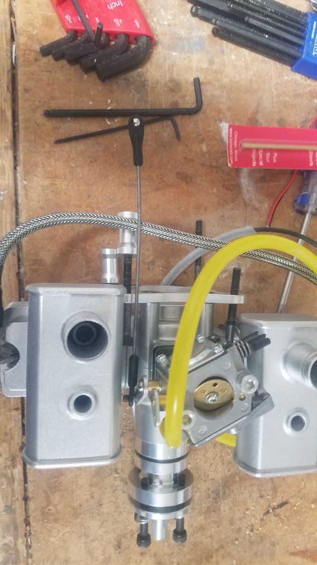
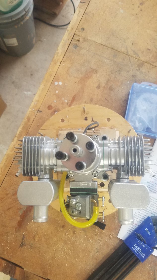
Muffler issue solved by using opposite muffler on needle value side and using the same muffler from the other engine on the opposite side. Had to order a new set of mufflers, but it was much less expensive than a custom-built set. One stack will be slightly forward but much better than full forward. Throttle linkage installed.
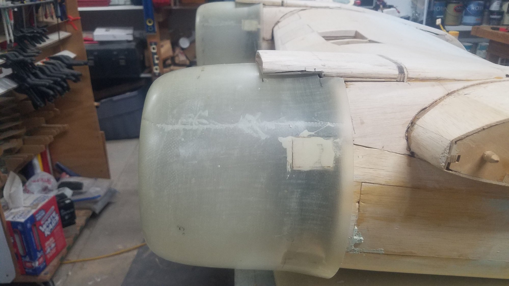
#1 Firewall mounted, cowl in place and air scoop glued in.
Painted firewall and scoop.
#2 Firewall mounted, cowl in place and air scoop glued in.
Painted firewall and scoop.
First try at using Easy Sand. Too much hardener on first attempt and it setup before I could use it. A little of this hardener goes a long way.
Muffler issue solved by using opposite muffler on needle value side and using the same muffler from the other engine on the opposite side. Had to order a new set of mufflers, but it was much less expensive than a custom-built set. One stack will be slightly forward but much better than full forward. Throttle linkage installed.
#1 Firewall mounted, cowl in place and air scoop glued in.
Painted firewall and scoop.
#2 Firewall mounted, cowl in place and air scoop glued in.
Painted firewall and scoop.
First try at using Easy Sand. Too much hardener on first attempt and it setup before I could use it. A little of this hardener goes a long way.
Last edited by rossmick; 10-01-2022 at 07:26 PM. Reason: Corrections
10-02-2022, 08:32 PM
#141
Senior Member
Thread Starter
Worked with Easy Sand (puddy). The original container of the puddy had lost its more liquid state and was more like a very thick paste. I decided to use the old with some of the new to loosen it up to do the rough layup. I used a small 1-1.5-inch puddle to mix to keep from losing the batch. This worked pretty well, but the mixture setup very quickly I think due to the mixing of the old and the new. I used very little hardener, because if I did not, I had that batch setup before I could get it all applied to the plane. Next, sanded and removed the air scoops and added additional reinforcement to the bolt down strip. I will clean up the scoops later. Then I beveled the edge of the firewalls so that there would a more open path for the air flow to the back of the cowl.
After Easy Sand (puddy) sanded, I used Bondo filler to get the low spots. This is more an experiment to see how to work with the puddy.
Roughing in the flare of the right ridge line.
Roughing in the flare of the left ridge line.
Will fill in the hatch door as I did on the right side. This hatch fit very well so there should not be too much filler to use here.
Beveled edges on the firewalls, to improve air flow.
First phase at reinforcing the hold down strip to the scoop. I'll clean this up later.
Last edited by rossmick; 10-02-2022 at 08:36 PM. Reason: Corrections
10-08-2022, 02:25 PM
#142
Senior Member
Thread Starter
Over the last several days I have been filling and sanding. It has created quite a mess with dust all over everything. It is so bad I had to stop and create a 4' x 2' downdraft sanding box. I made this up out of material I already had, and I needed it big enough for the large pieces but able to be stored under one of my work benches. I chose alum. sided 1" foam board for the sides,1/8" hardboard for the baffles and peg board for the top. Large Gorilla tap used for the seams to make it airtight. Put in air gates on the vacuum system.so that I can select air for the box or air for all the tools. This works way better than I thought and am very pleased in how it went together. The foam has kept the weight down, so it is easy to move around and store.
I haven't got too many more days to work on the plane as we are leaving in 10 days or so for a 5-week trip with 5th wheel to visit family and friends. I'll see how much more I can get done before departure. The 3/4 oz. fiberglass cloth should show up before I leave and will most likely be the next step when I get back. I've decided to use polyacrylic to fill the weave as there is no smell and it is easy to clean up. The drawback is that it takes more coats and more time to dry between the coats, but outcome is the same or better than epoxy.
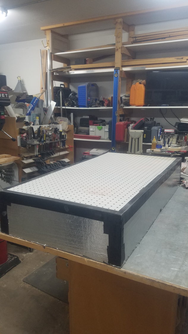
4' x 2' downdraft sanding box. This is light weight and will slide under one of the work benches when not in use.
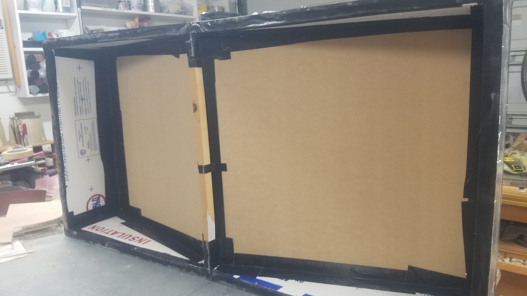
Alum. sided 1" foam board with 1/8" hardboard baffles. I used a 1x1 to brace the baffle at the center as well as another 1x1 cross member at the center for the top peg board. Large Gorilla tape used for all the seams inside and out, doubled up in many locations.
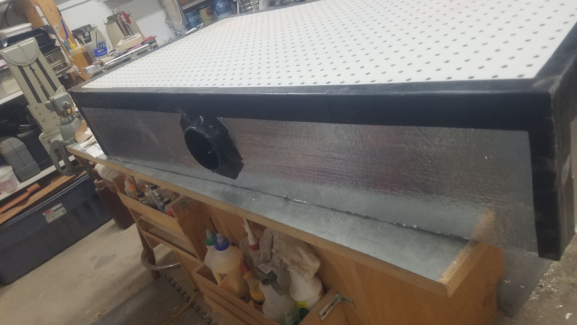
Standard air connecter was carefully cut in and tape used to seal it up on both sides.
4" air hose connected
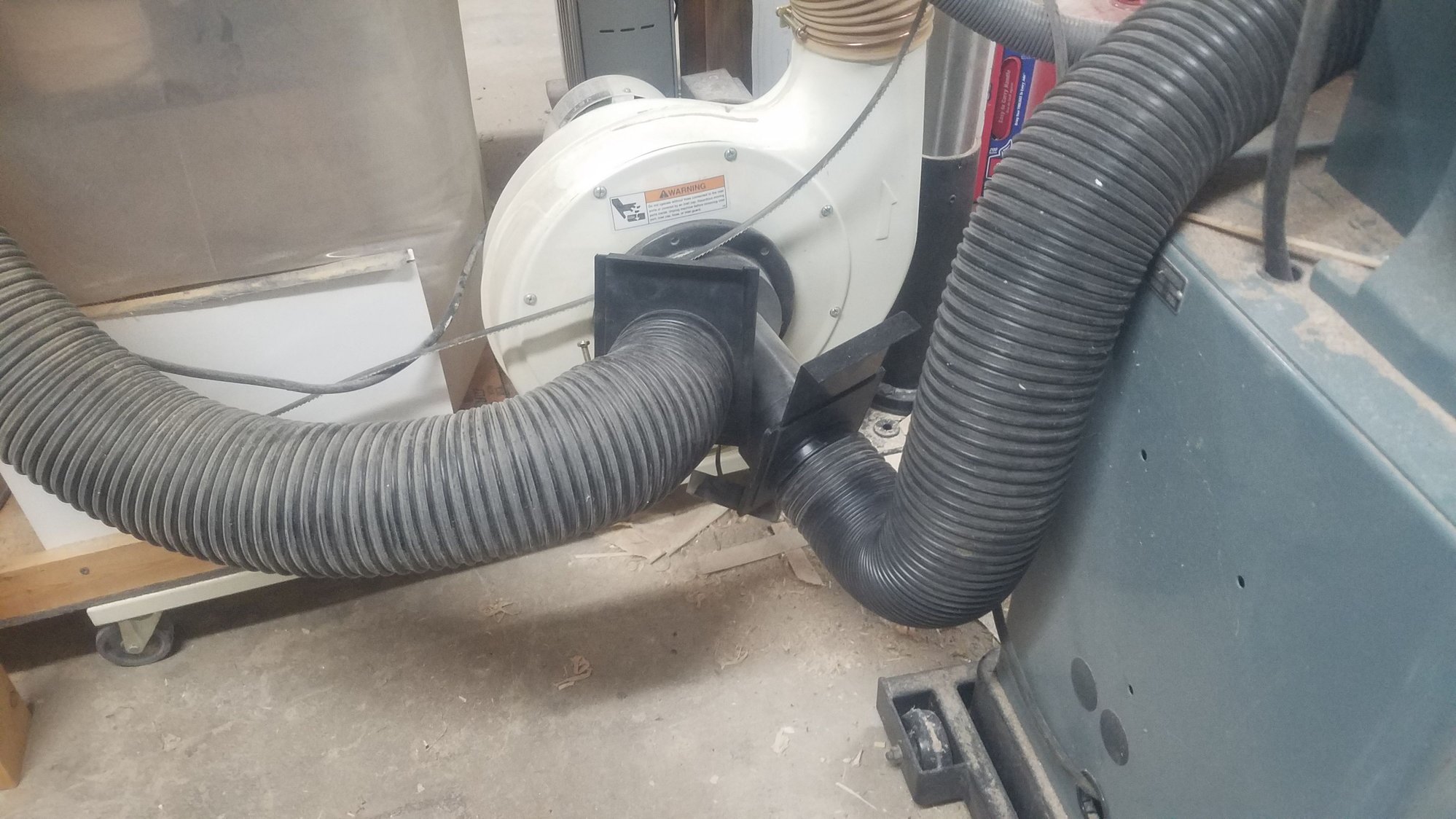
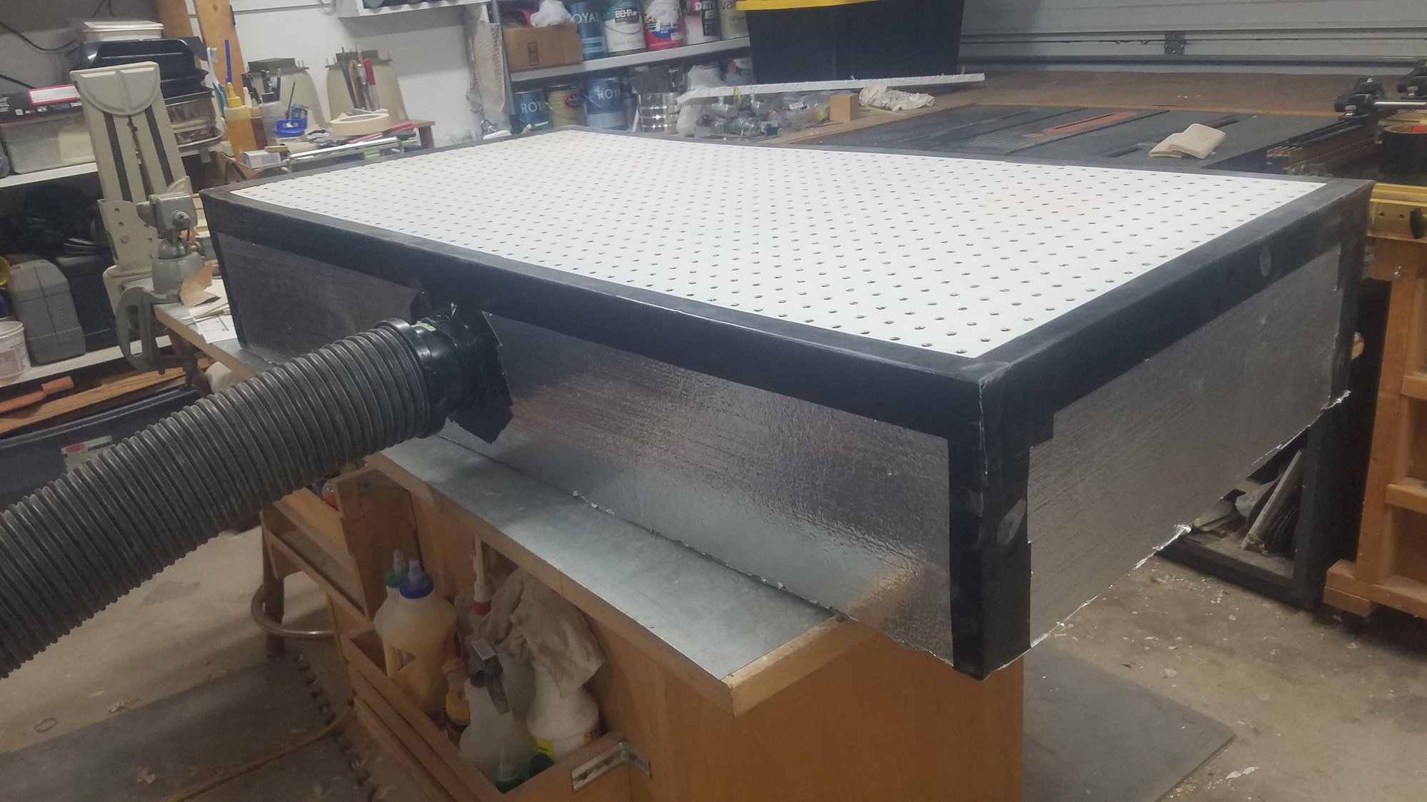
I have a split gate arrangement so that I can open a gate for the sanding box or open a gate for all the other tools. I tried both gates open and still had good airflow at the sanding box but will keep the tools gate closed when using the sanding box. Air flow at the box is very strong when just using the single gate.
Needed a larger sanding box for the larger pieces. With the baffles, the suction is very even over the whole surface.
I am well pleased with how this is working, and only wish now that I would have built this a long time ago to save the shop from all the dust and all the time it took to clean it all up.
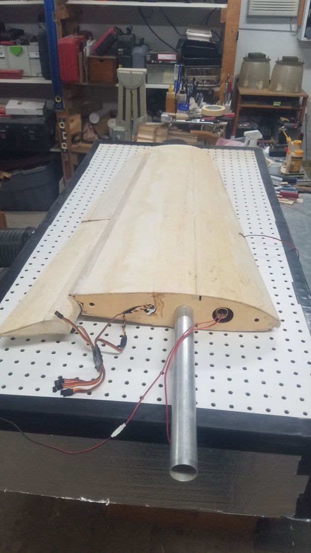
Just shows largest piece handled by sanding box. This worked really well as material got sucked in, and what fell on the top got picked up when I used a brush to sweep it off.
I haven't got too many more days to work on the plane as we are leaving in 10 days or so for a 5-week trip with 5th wheel to visit family and friends. I'll see how much more I can get done before departure. The 3/4 oz. fiberglass cloth should show up before I leave and will most likely be the next step when I get back. I've decided to use polyacrylic to fill the weave as there is no smell and it is easy to clean up. The drawback is that it takes more coats and more time to dry between the coats, but outcome is the same or better than epoxy.
4' x 2' downdraft sanding box. This is light weight and will slide under one of the work benches when not in use.
Alum. sided 1" foam board with 1/8" hardboard baffles. I used a 1x1 to brace the baffle at the center as well as another 1x1 cross member at the center for the top peg board. Large Gorilla tape used for all the seams inside and out, doubled up in many locations.
Standard air connecter was carefully cut in and tape used to seal it up on both sides.
4" air hose connected
I have a split gate arrangement so that I can open a gate for the sanding box or open a gate for all the other tools. I tried both gates open and still had good airflow at the sanding box but will keep the tools gate closed when using the sanding box. Air flow at the box is very strong when just using the single gate.
Needed a larger sanding box for the larger pieces. With the baffles, the suction is very even over the whole surface.
I am well pleased with how this is working, and only wish now that I would have built this a long time ago to save the shop from all the dust and all the time it took to clean it all up.
Just shows largest piece handled by sanding box. This worked really well as material got sucked in, and what fell on the top got picked up when I used a brush to sweep it off.
Last edited by rossmick; 10-08-2022 at 03:04 PM. Reason: Corrections
10-10-2022, 07:17 PM
#143
Senior Member
Thread Starter
Spent the majority of the day finish cleaning the shop. Created additional shelfs for the charging, battery storage and radio cases. Stored the vacuum sanding unit but will use it shortly. I did get some work done on the center section flaps to make them more scale.
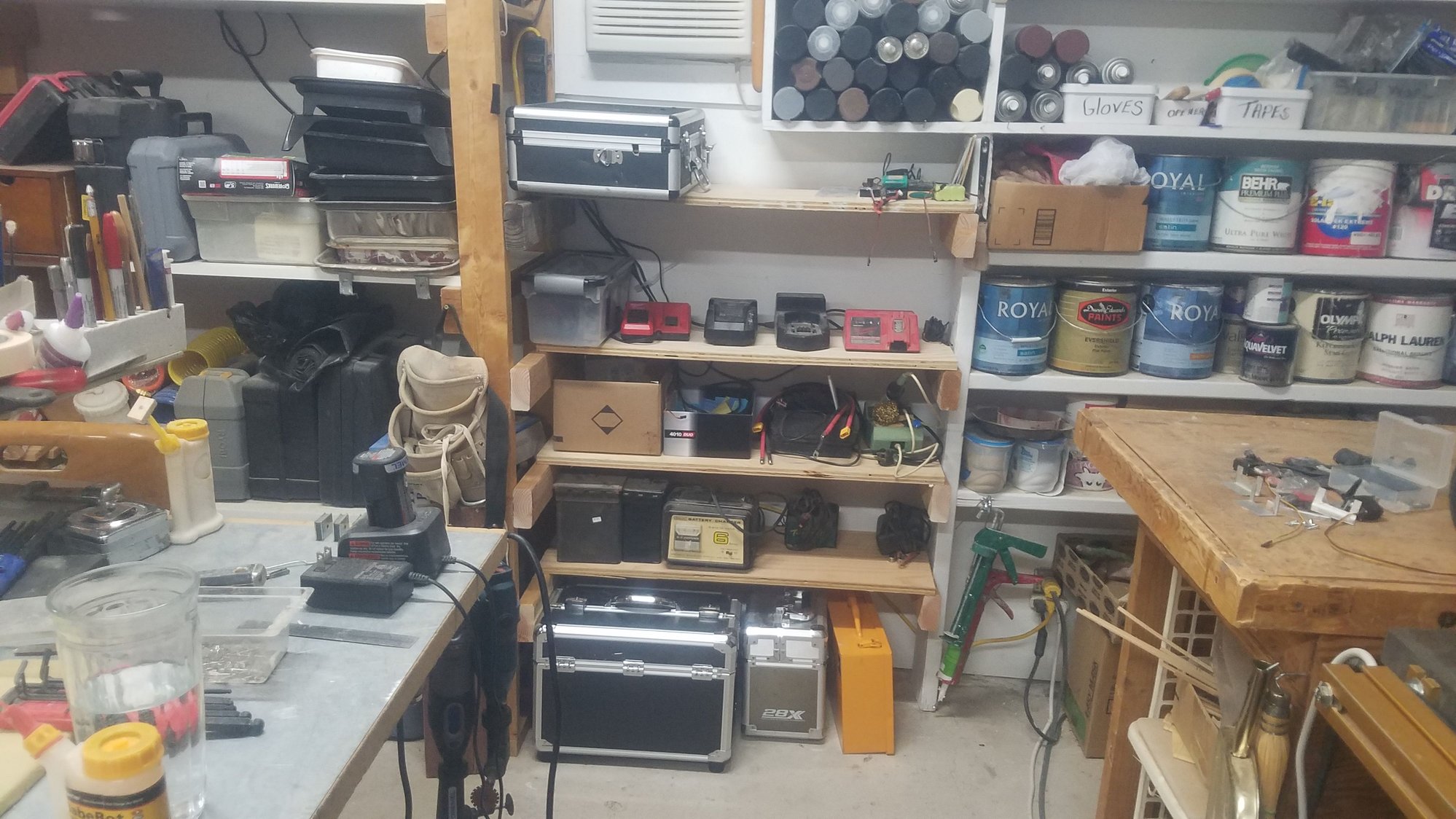
Increased the storage area for the chargers, the battery storage, both good and bad, and an area for the radio cases.
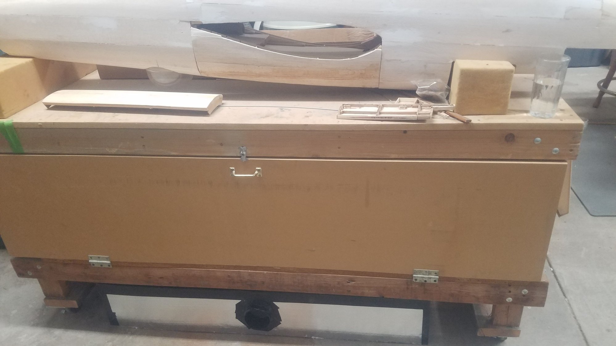
Down draft sanding box in its storage location.
Left flap being modified for a more scale look.
Right flap modified, more work to be done on the flaps to get them correct.
Flap opening reshaped to get to scale
Working on the other flap opening, I am changing the way the plan showed how to do the flaps to get to scale.
Increased the storage area for the chargers, the battery storage, both good and bad, and an area for the radio cases.
Down draft sanding box in its storage location.
Left flap being modified for a more scale look.
Right flap modified, more work to be done on the flaps to get them correct.
Flap opening reshaped to get to scale
Working on the other flap opening, I am changing the way the plan showed how to do the flaps to get to scale.
10-11-2022, 06:45 PM
#144
Senior Member
Thread Starter
Got in a solid day and got central flaps change to be scale and to have adequate clearance. Also created servo mounts and got the throttle servos installed after remounting the engines to the removable firewalls.
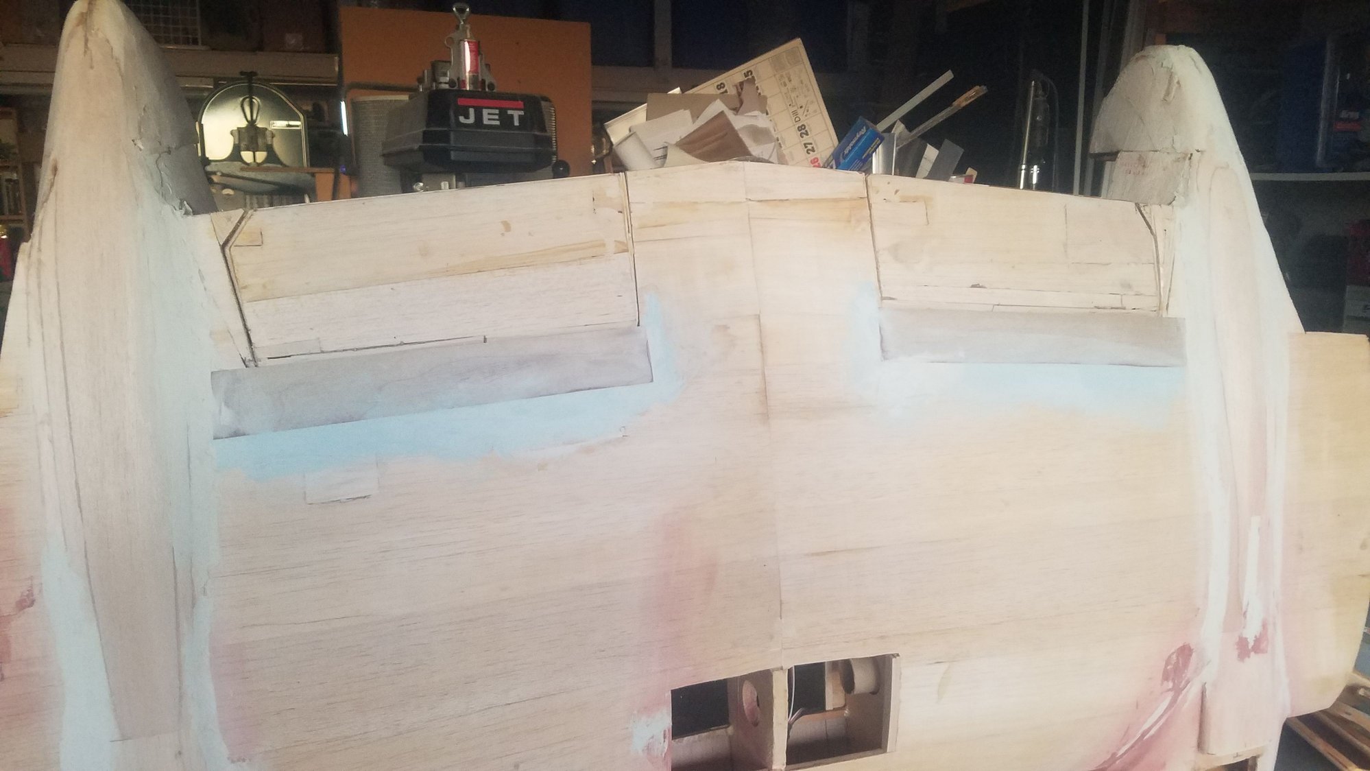
Getting close to having the central flaps as scale as possible. Need to do final sanding for better clearance and transition to the fuselage.
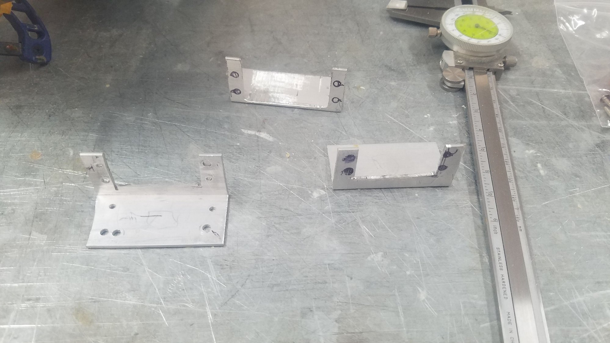
Servo mounts made from alum. angle that is sawed out with 8 holes drilled.
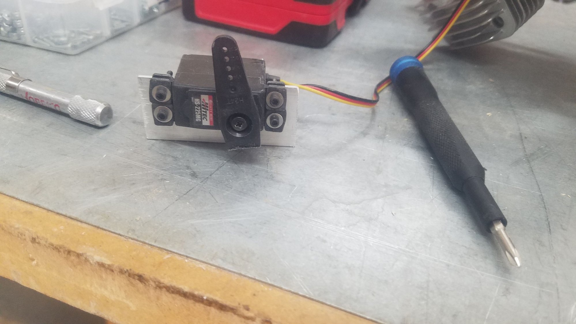
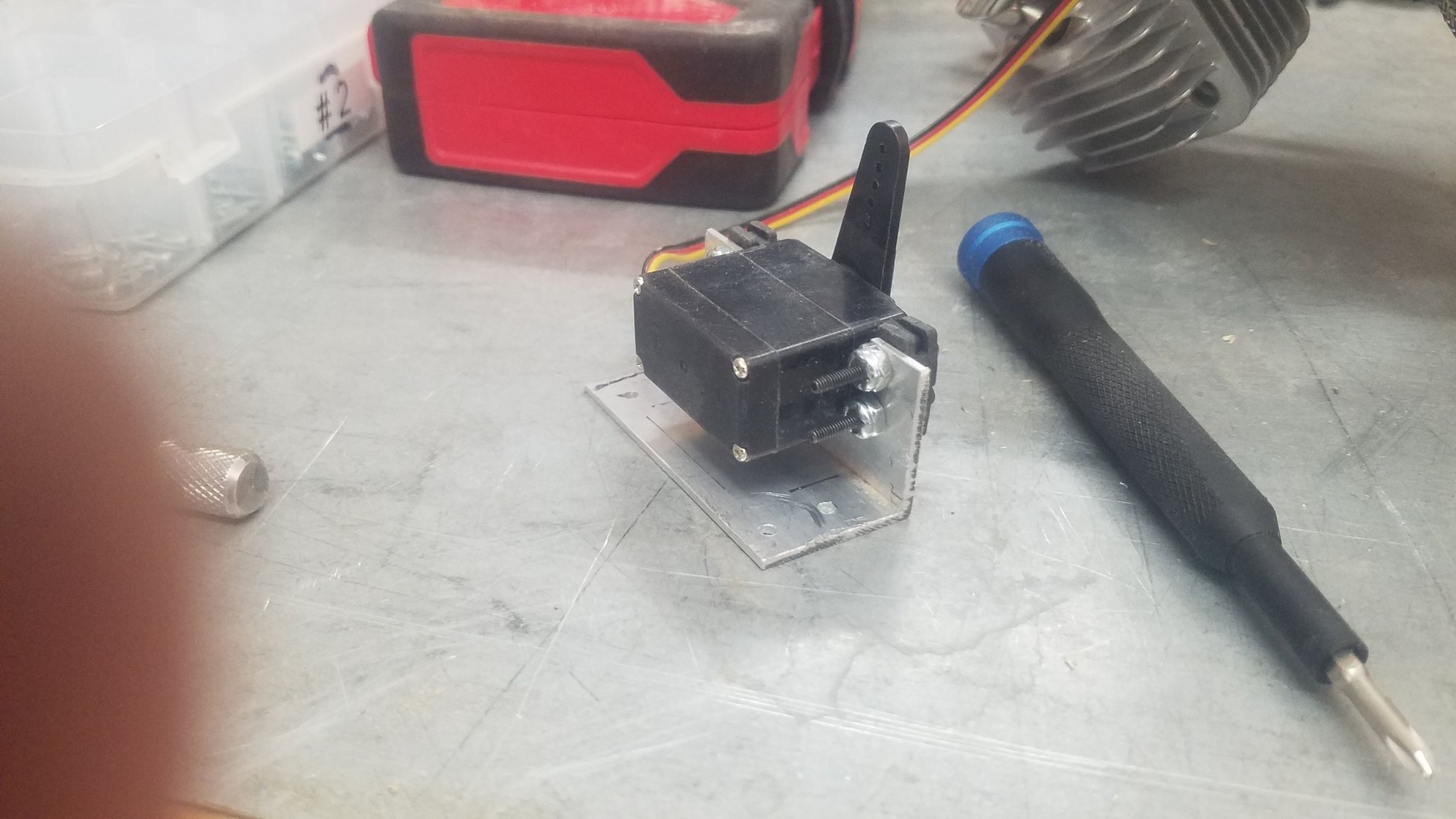
Servo bolted in the mount.
I used bolts and nylock nuts to attach the servo. I think the angle is too thin to tap for the servo mounts and have enough strength to hold the servo. I ran out of shorter bolts so had to use the longer ones. I may cut them shorter but may not bother with it.
Mounted the servo with 4 screws and attached the throttle linkage after putting the bras tube around the threaded push rod.
The other engine throttle servo mounted and attached.
Need to install the ignition unit on the one firewall. Getting close on being done on engine install.
Getting close to having the central flaps as scale as possible. Need to do final sanding for better clearance and transition to the fuselage.
Servo mounts made from alum. angle that is sawed out with 8 holes drilled.
Servo bolted in the mount.
I used bolts and nylock nuts to attach the servo. I think the angle is too thin to tap for the servo mounts and have enough strength to hold the servo. I ran out of shorter bolts so had to use the longer ones. I may cut them shorter but may not bother with it.
Mounted the servo with 4 screws and attached the throttle linkage after putting the bras tube around the threaded push rod.
The other engine throttle servo mounted and attached.
Need to install the ignition unit on the one firewall. Getting close on being done on engine install.
Last edited by rossmick; 10-11-2022 at 06:50 PM. Reason: Added information
12-20-2022, 06:55 PM
#146
Senior Member
Thread Starter
Back from vacation and after many catch up projects, I have gotten back to the B25. One of the projects was installing an electric garage heater to allow me to work much more during the winter months. Believe it or not, it gets cold in Tucson, so this is a nice addition. There was also a little hesitation because of the mess with the main gear doors. I used the build in place and cut out method which was fine at first but after several years setting on the shelf, they no longer are the correct shape. Also, I did a just terrible job at the N5 former, and it is a mess. Spent most of the day trying to figure out how to correct the errors and how to reshape the doors. The doors line up fine at the front but no longer meet N5 correctly. This will be an interesting fix. Another issue is the gear itself is very large and the doors have to be trimmed to get them to fit. I am adding fillers to correct this area around the N5 and after sanding, hopefully it will correct the error.
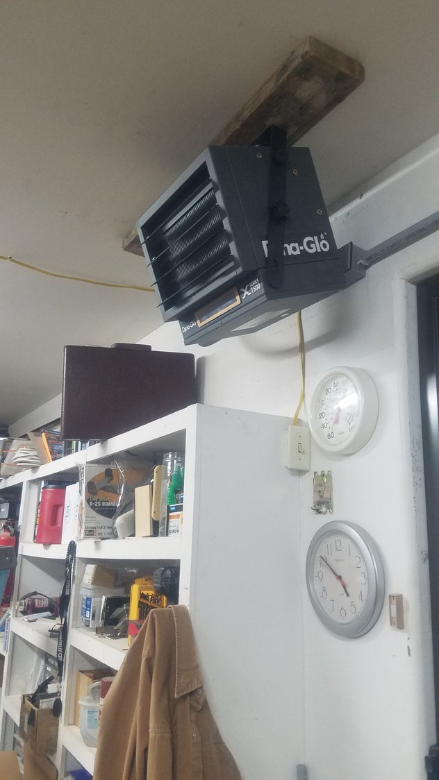
Electric heater installed. Running the #8 220 wire was a challenge. It's a 7500-watt unit and does a nice job of bringing the temperature up. It's a dual unit so only runs at 7500 for a short time and then drops to 5000 when within about 5 degrees of selected temp.
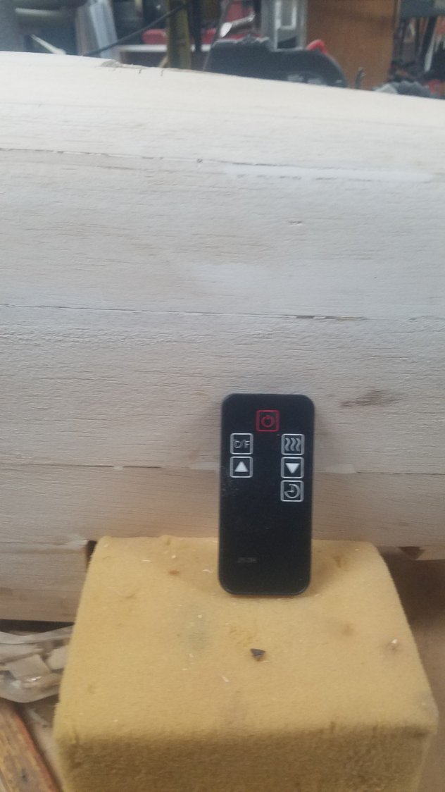
Remote for the heater was a nice addition.
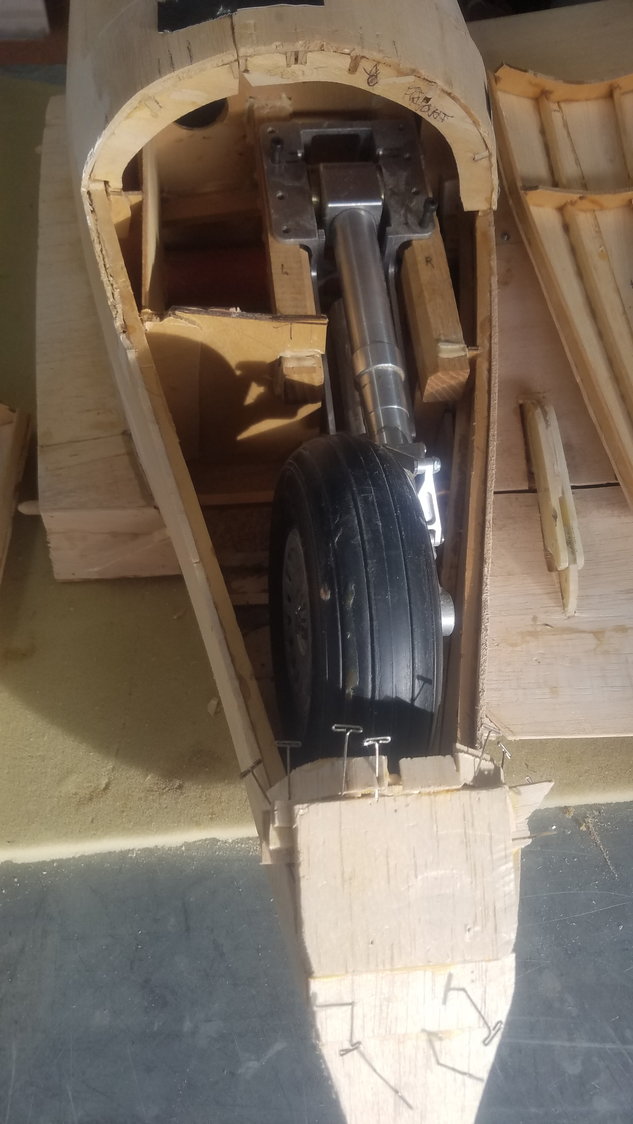
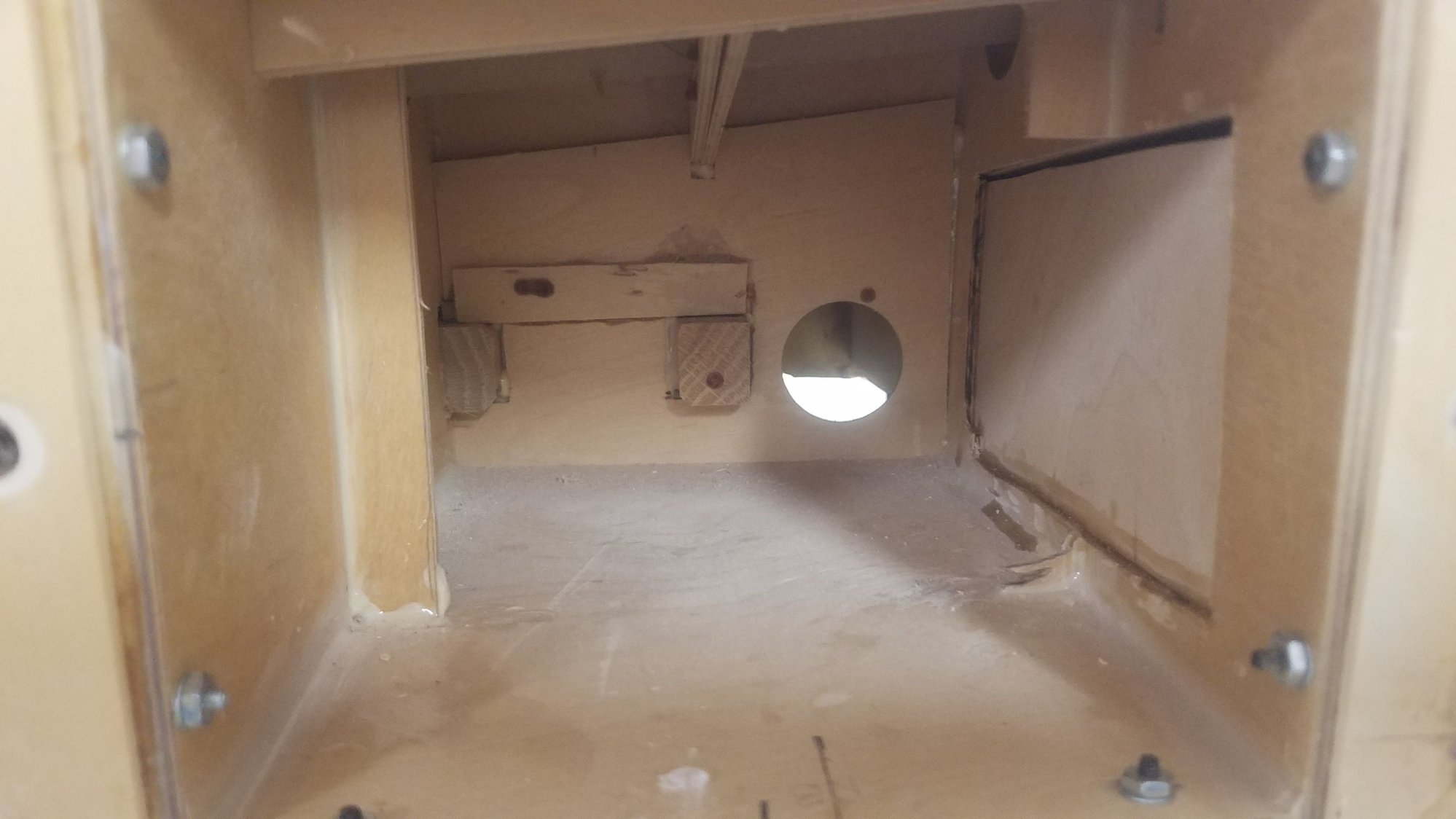
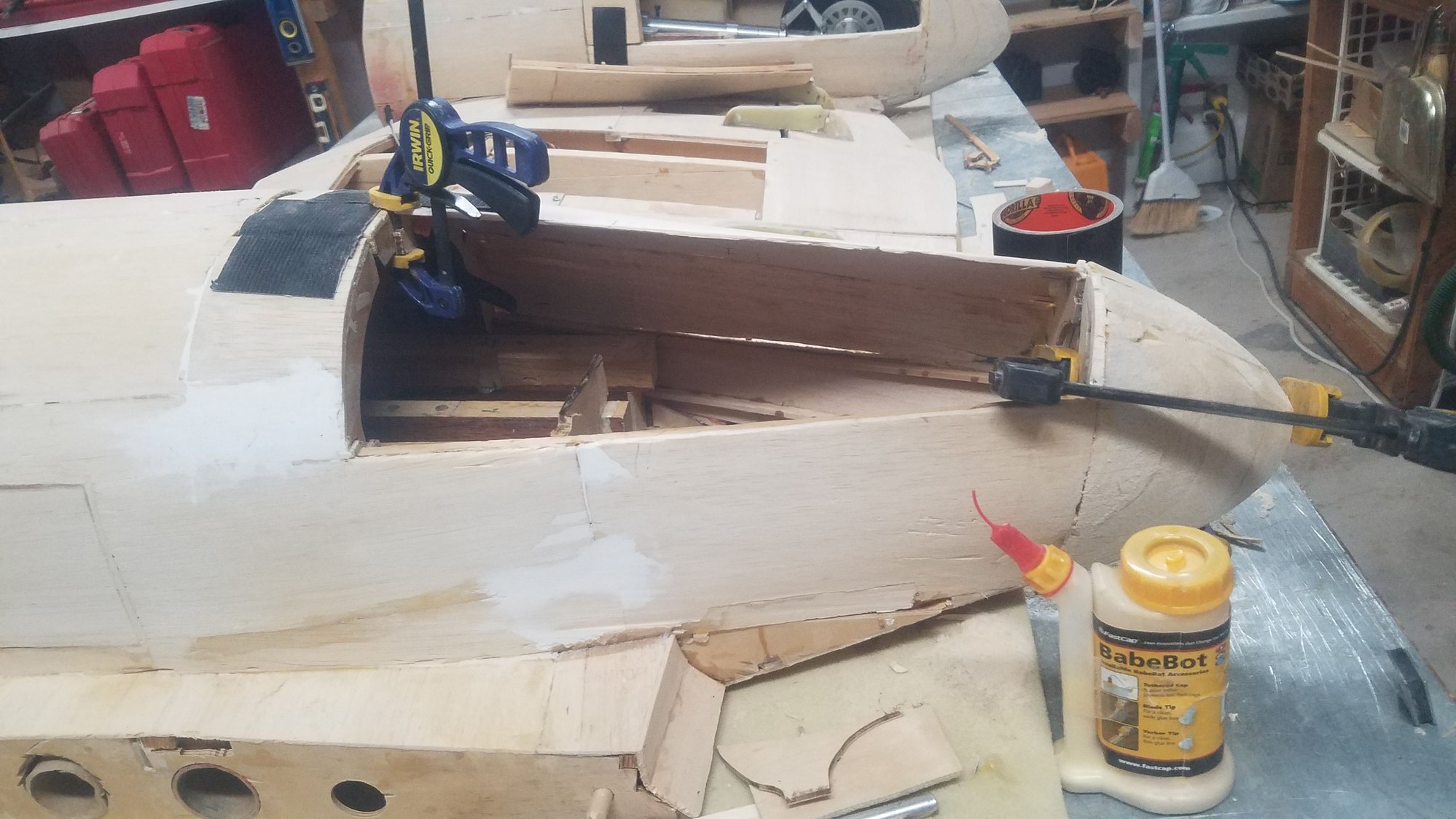
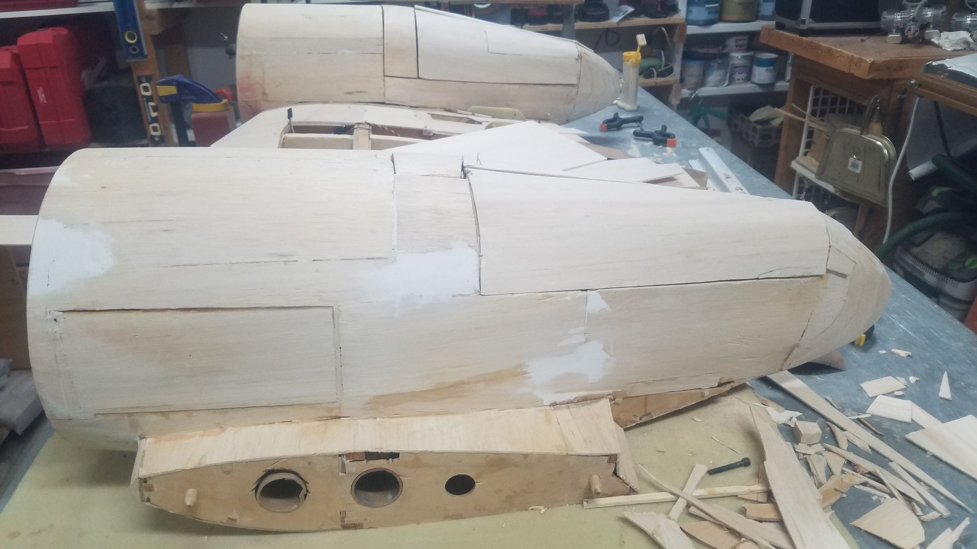
Right main in position. Patching around N5.
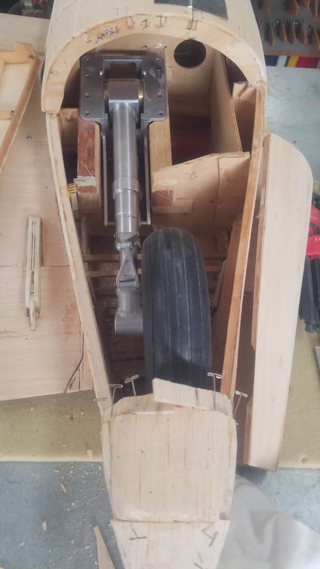
Left main in position. Patching around N5.
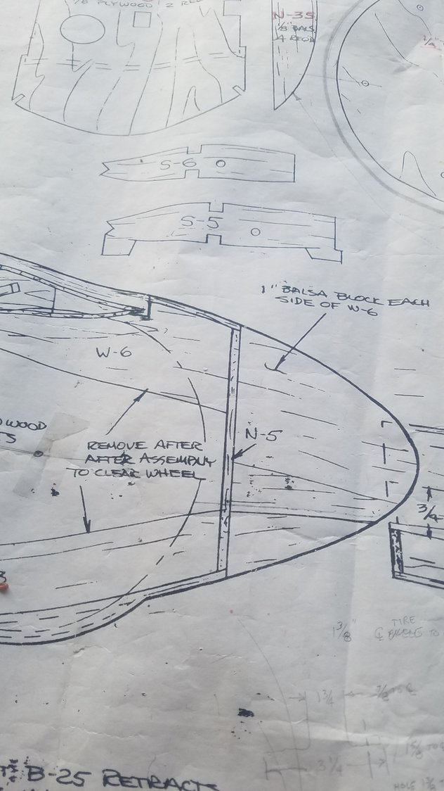
N5 former drawing. Note I will not have the bump in the doors for the gear.
I have removed the rear former at the end of all the doors and will try and reform them to meet N5. I'm not sure if this is going to work as I may need another former just in front of the wheel to get the correct shape.
Note, that the doors are different sizes at each gear location. This is the large door.
This is the small door
I must fill in the cut out I made to miss the wheel. After doing more trimming inside the well I am able to keep the wheel inside the doors, I hope.
Electric heater installed. Running the #8 220 wire was a challenge. It's a 7500-watt unit and does a nice job of bringing the temperature up. It's a dual unit so only runs at 7500 for a short time and then drops to 5000 when within about 5 degrees of selected temp.
Remote for the heater was a nice addition.
Right main in position. Patching around N5.
Left main in position. Patching around N5.
N5 former drawing. Note I will not have the bump in the doors for the gear.
I have removed the rear former at the end of all the doors and will try and reform them to meet N5. I'm not sure if this is going to work as I may need another former just in front of the wheel to get the correct shape.
Note, that the doors are different sizes at each gear location. This is the large door.
This is the small door
I must fill in the cut out I made to miss the wheel. After doing more trimming inside the well I am able to keep the wheel inside the doors, I hope.
12-22-2022, 08:05 PM
#147
Senior Member
Thread Starter
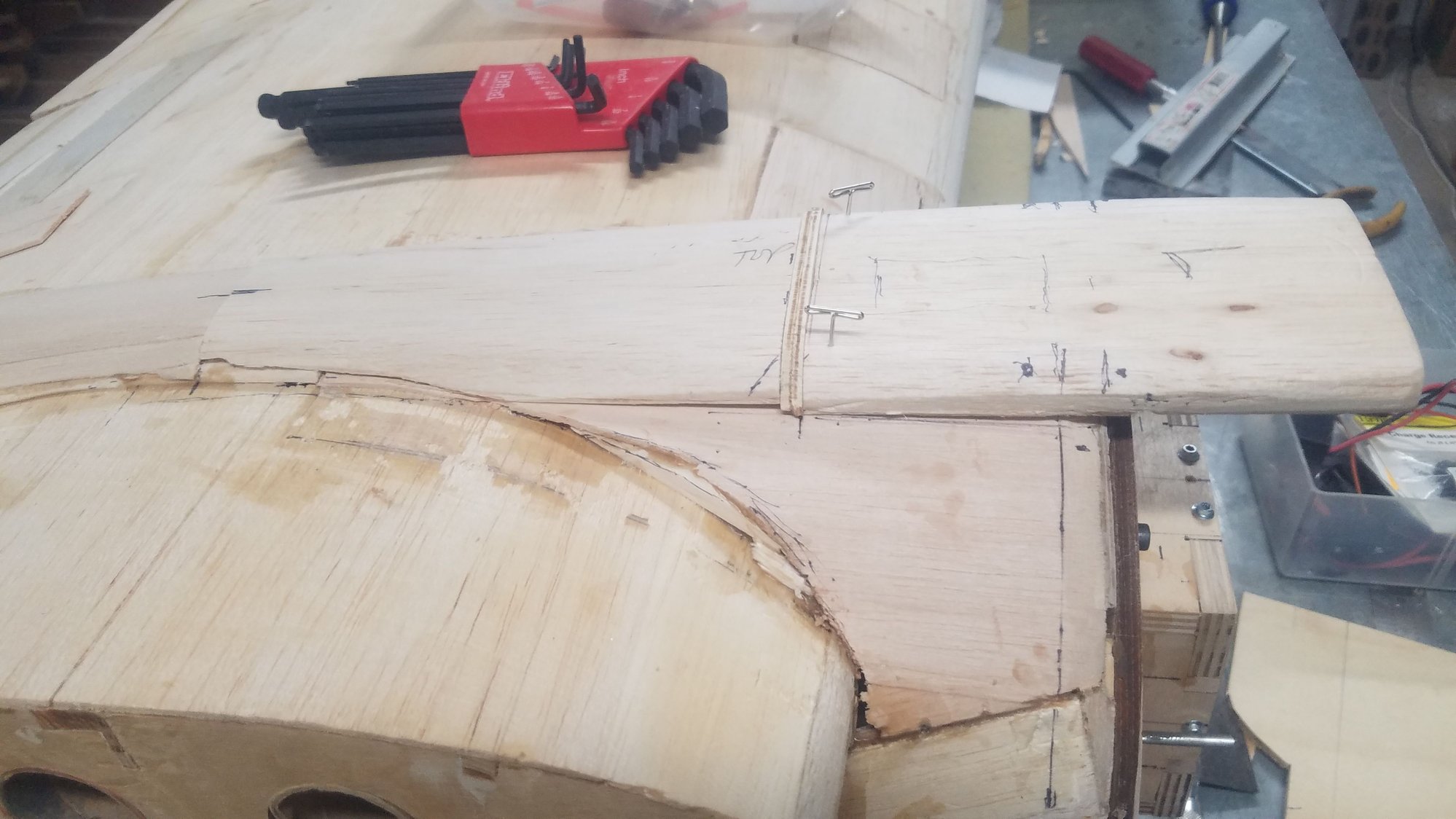
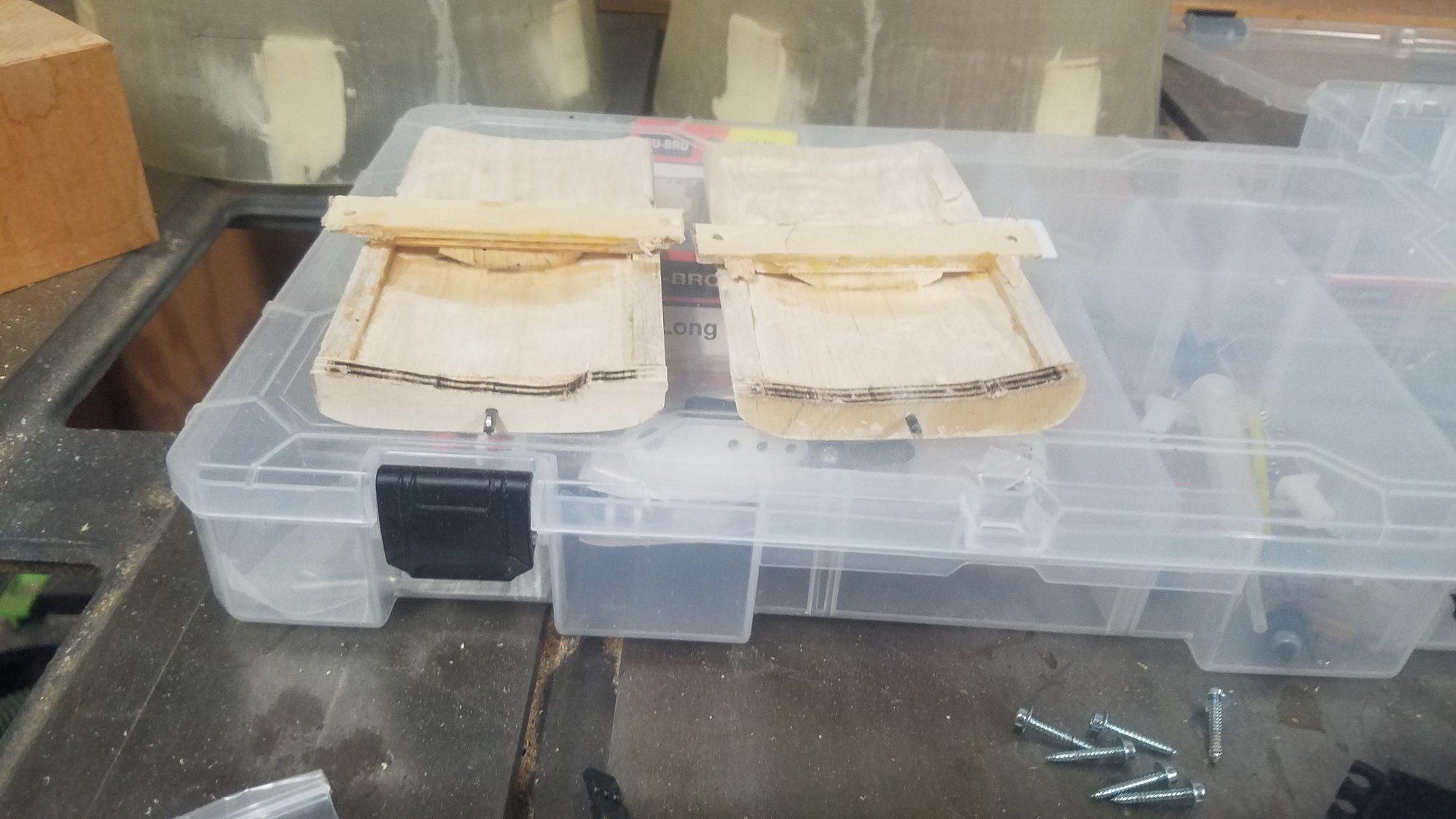
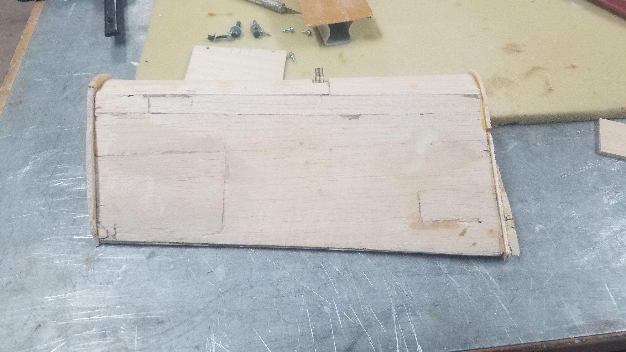
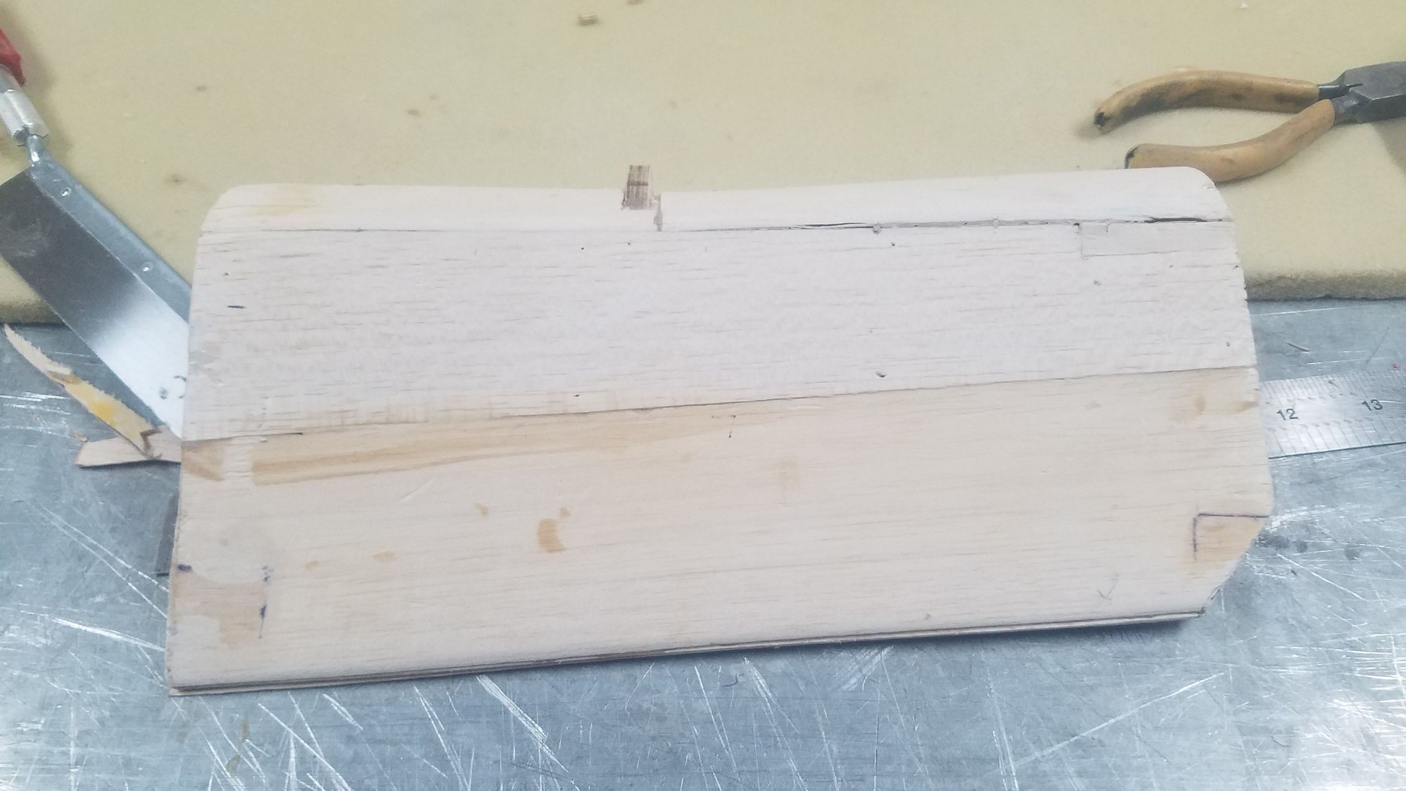
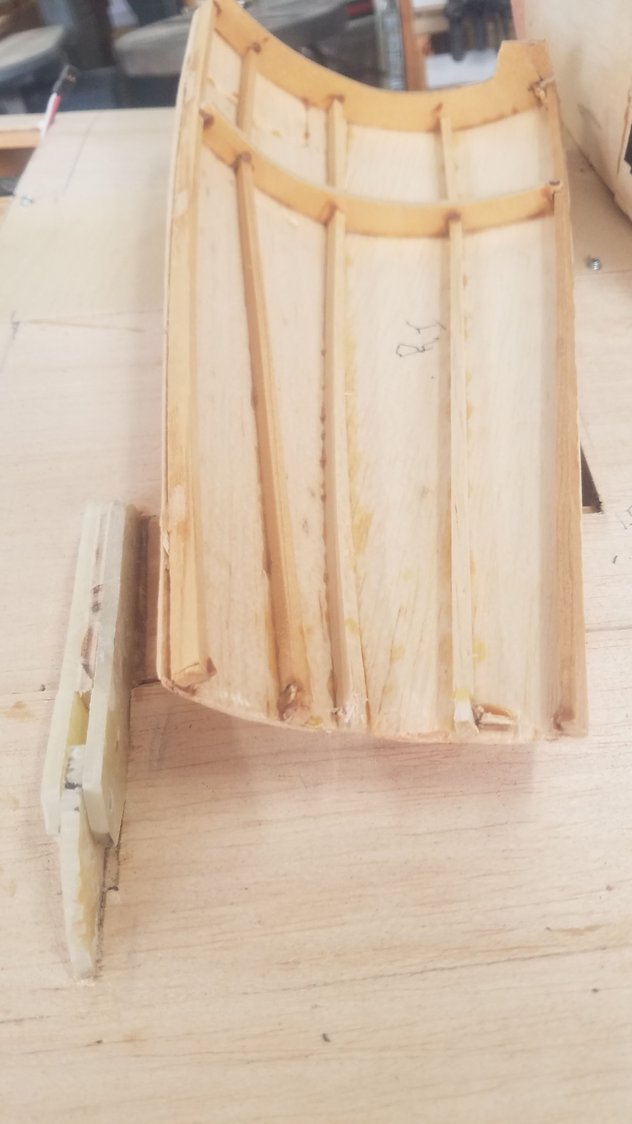
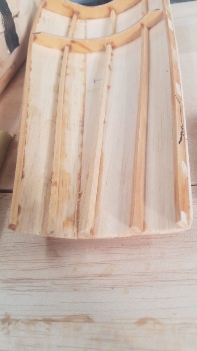
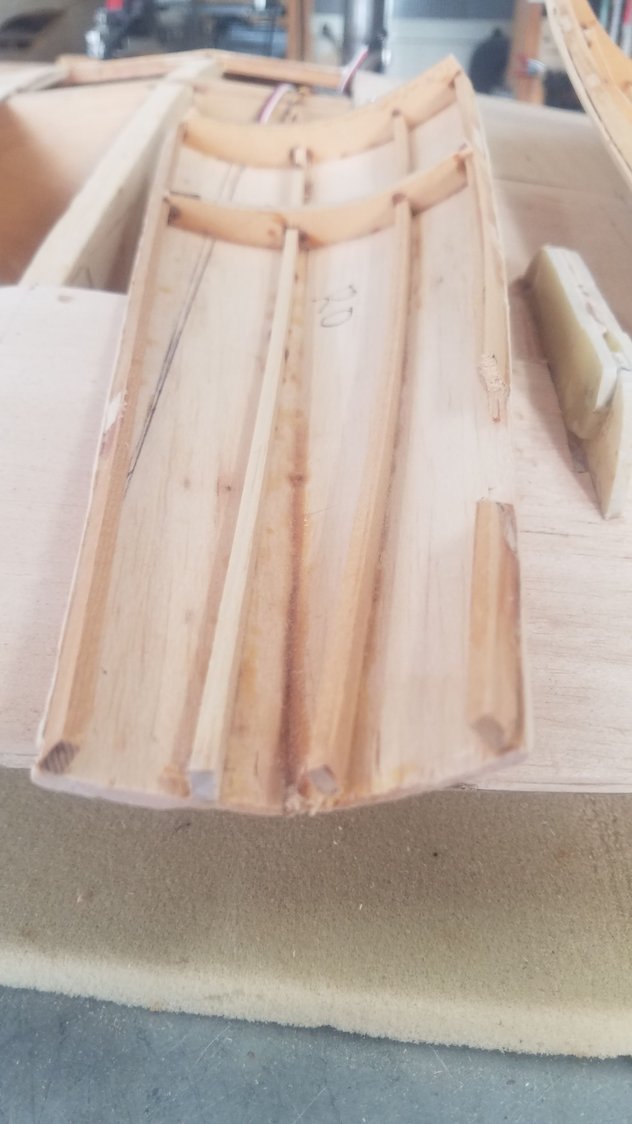
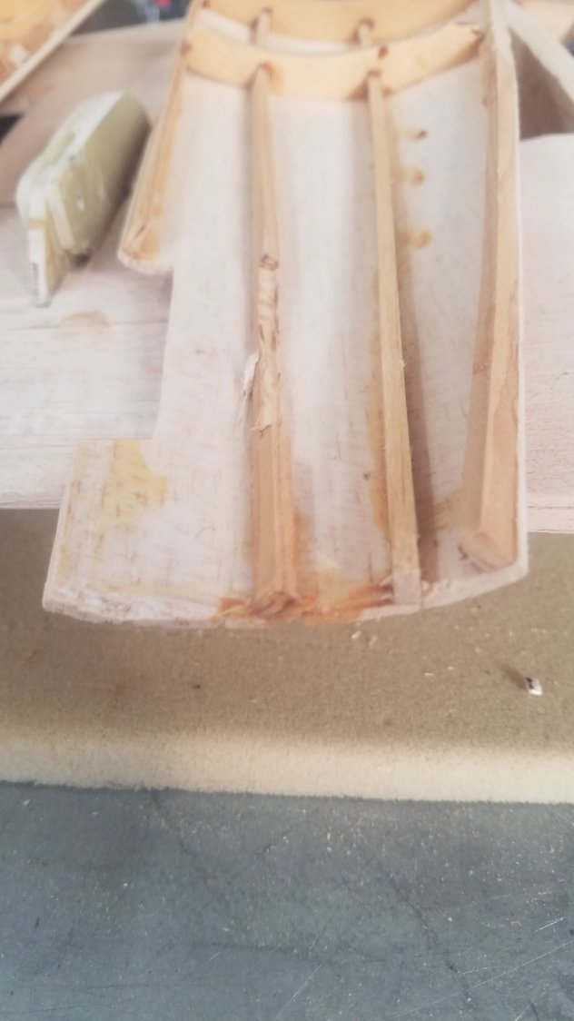
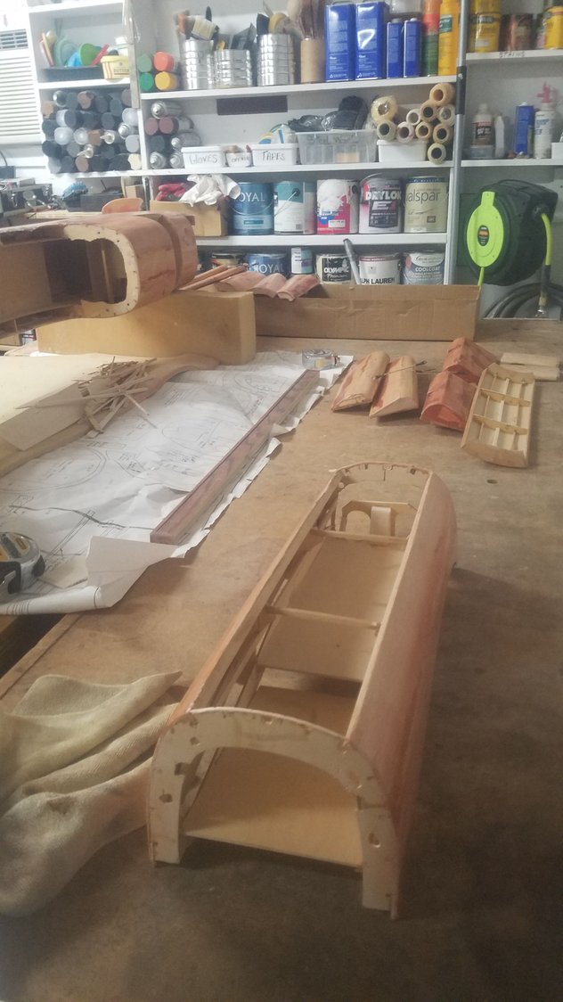
Sent hours trying to warp the doors back to shape with no success. Decided to strip the skin of the stringers and formers. I cut new end formers to improve the shape to match the front and rear sections. I'll see if this approach works.
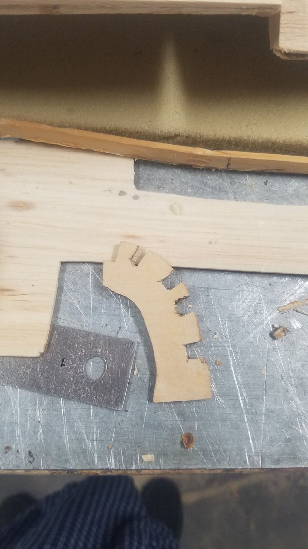
Cut new rear former to match the back location from a template. This may have to be done over to reposition the cuts for the stringers.
Front and rear formers tacked in and held in place. A new center former will have to be made and glued in after the stringers are installed. There are no stringers at this time.
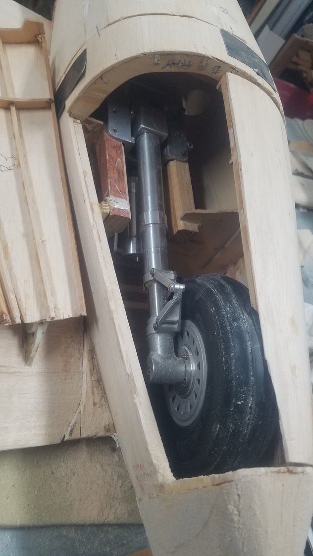
Getting close and now need to navigate around the wheel with the stringers.
Cut new rear former to match the back location from a template. This may have to be done over to reposition the cuts for the stringers.
Front and rear formers tacked in and held in place. A new center former will have to be made and glued in after the stringers are installed. There are no stringers at this time.
Getting close and now need to navigate around the wheel with the stringers.
01-12-2023, 07:32 PM
#148
Senior Member
Thread Starter
Haven't posted for a while but I have been working on the main gear doors. I am on my third attempt to get them to fit correctly. Every once in a while, you hit a roadblock and you just have to stay at it to get past the problem. I gave up after a while trying to make the original doors work, and just rebuilt new doors in place only using the spruce stringers on the outside edges. Even then, I still have issues with the warping from the front of the doors to the rear. Also discovered that I was not careful enough when installing the gear mounts and one was 1/8" higher than the other. After modifying the mount, the gear will now fit inside the doors when they are closed. Doors aren't perfect yet, but they are getting better and will need some build up around the edges to make a nice snug fit. Found it was necessary to build up the tail cone area to help the doors miss the wheel and will sand it to shape after doors are hinged in place.
Last edited by rossmick; 01-12-2023 at 07:39 PM.
03-14-2023, 09:33 PM
#149
Senior Member
Thread Starter
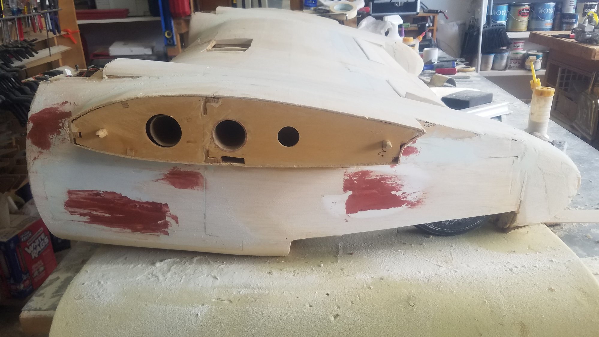
Haven't posted in a while but I have been working on the plane. The main gear doors literally stop me for a month, ended up remaking them 3 times before I could get them correct. I took a break as I was pretty fed up with the slow progress but picked things back up about 2 weeks ago. I took a great deal of time filling the voids and nicks with Bondo glazing and spot putty. I found it was easy to apply and sands out really well. Only problem is that it shrinks, so it takes several applications to fill a low spot. I have learned a lesson that I should have spent more time in getting the balsa applied much more smoothly with less low areas and dings.
I am applying the 3/4 oz. fiberglass using Minwax polyacrylic and found that it is easier to work with than epoxy. It takes more coats, about 6, it is very easy to apply with a 3" foam brush and sands out very well. It's all a new experience but seems to be working well. Some say wait 2 hours and re-apply, I usually wait overnight which makes the surface much harder. Poly is much easier to apply than epoxy, just brush it on, with no smell and cleans up with water. As it is water based you have to coat the balsa with lacquer wood sealer first to keep the water in the poly from warping the wood. I did a quick sanding after the filler dried and then started the poly application. The photos show the progress so far and I will try and post as more work is done.
One thing that I am sure of is that you have to like to sand, and I haven't even gotten to the primer yet.
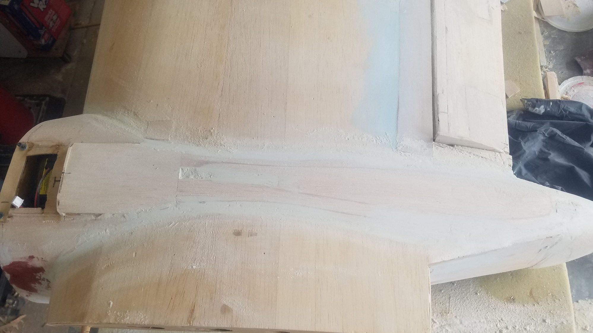
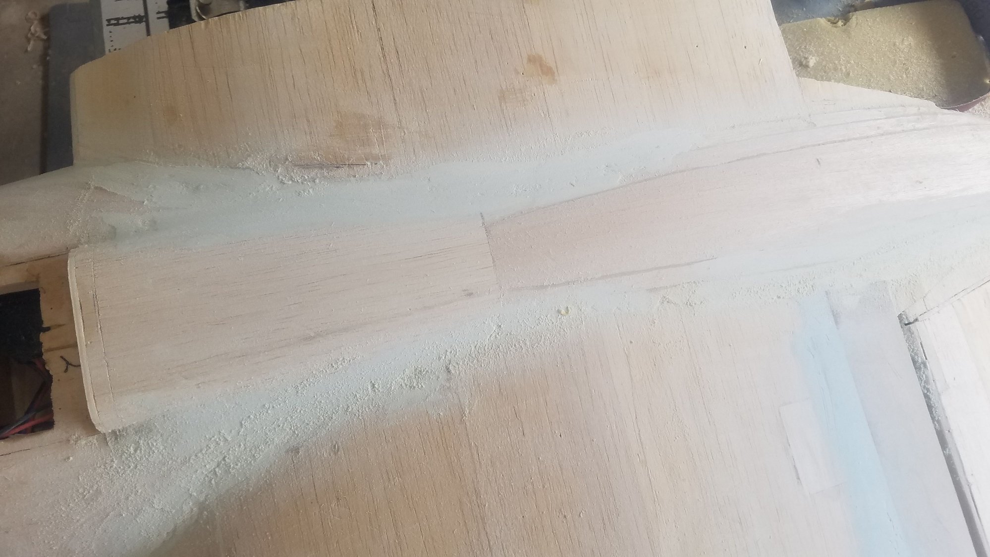
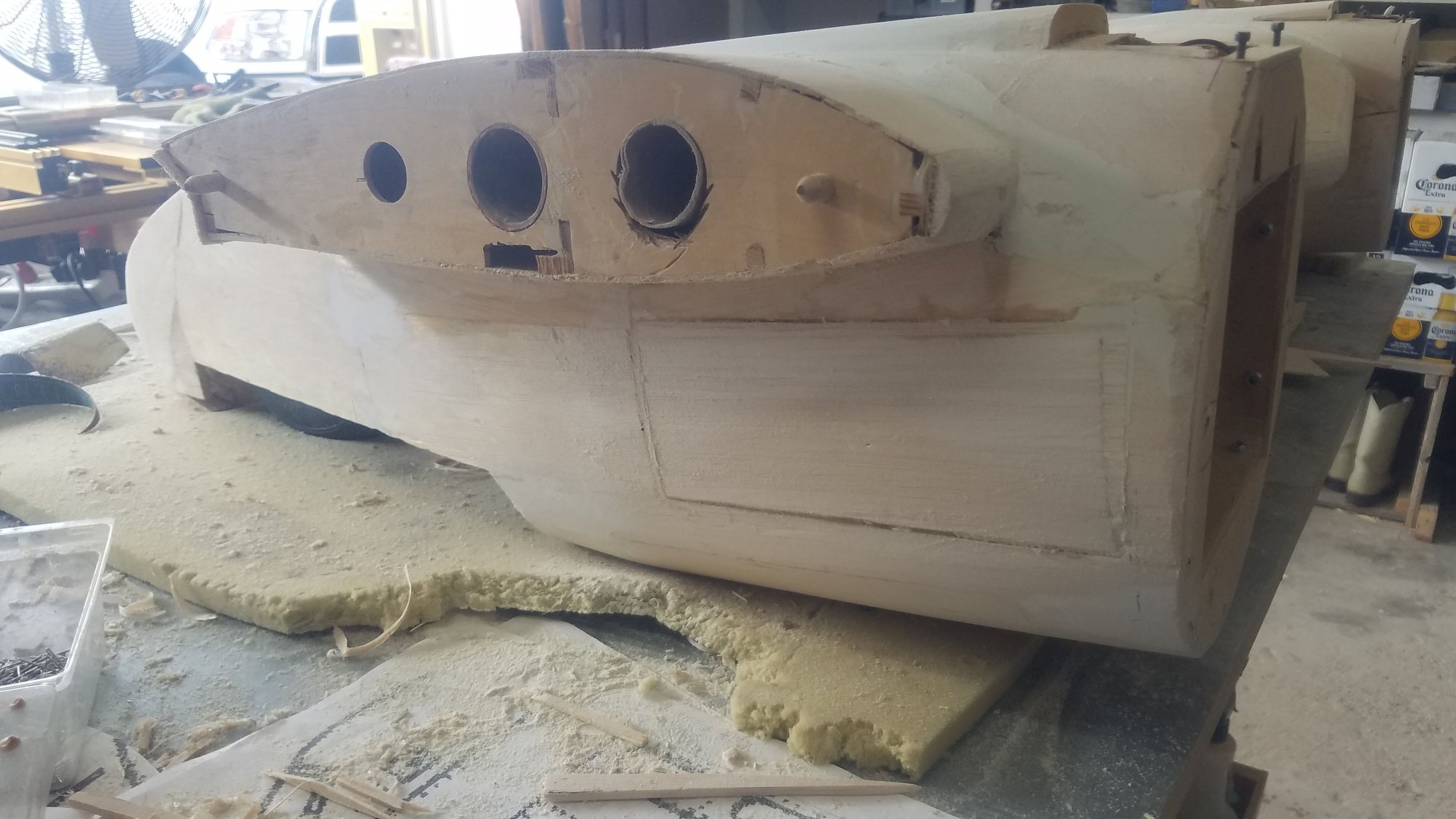
As I wait for the poly to dry on the other parts, I continue the filling of the low areas and fillets on the center nacelle. It will be the next section to get the poly applied. It will be a little tricky with all the curved surfaces, but I will try doing it in sections. I am not sure how it will handle the fillets.
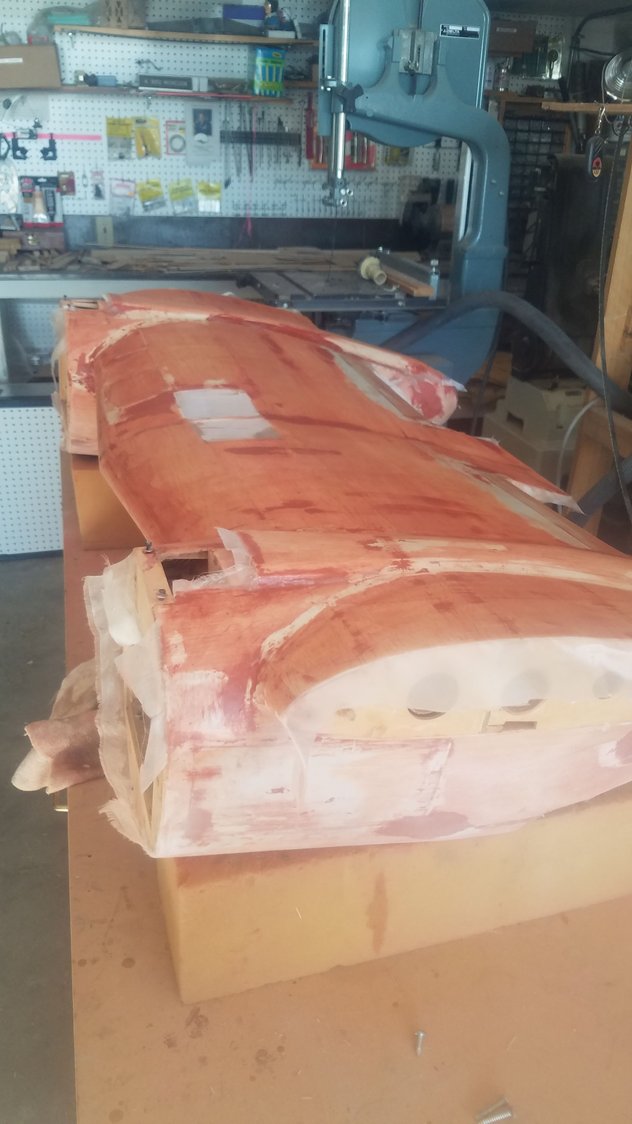
Tail section will take some more work as the skin was sanded so thin that it just broke through when I picked it up. The bad area is on the other side and should be the last area to work on to finish the poly work. I will leave the vertical fins off and after finishing the poly will then glue them in place.
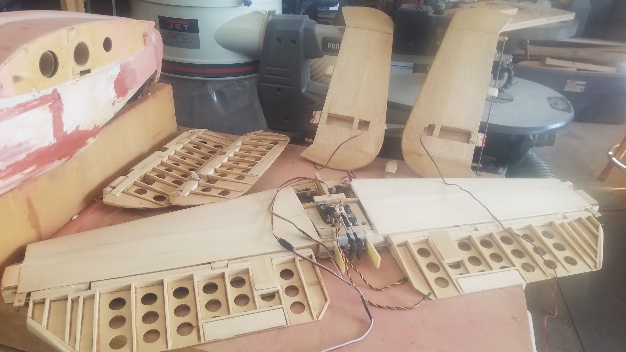
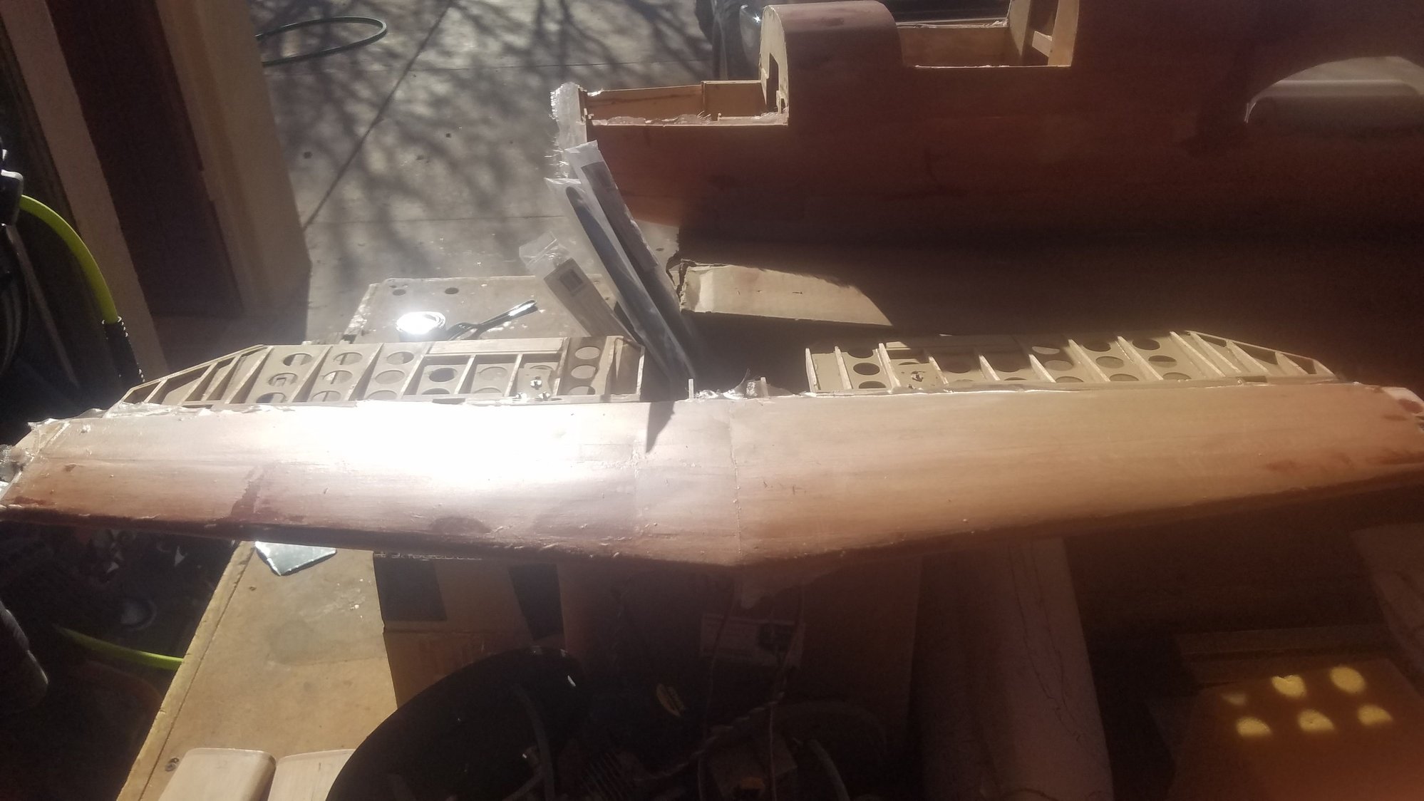
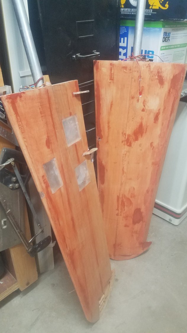
Wings with both sides glassed but will need more sanding and additional coats. The leading edge is double lapped so it should be somewhat stronger for possible hanger rash.
All hatch covers and small main gear doors covered and sanded. They will be the first parts to get sprayed with filler primer.
Flaps, ailerons, top hatch and the gear doors covered and will need one more sanding and more coats.
Poly coming up very smooth on finished parts.
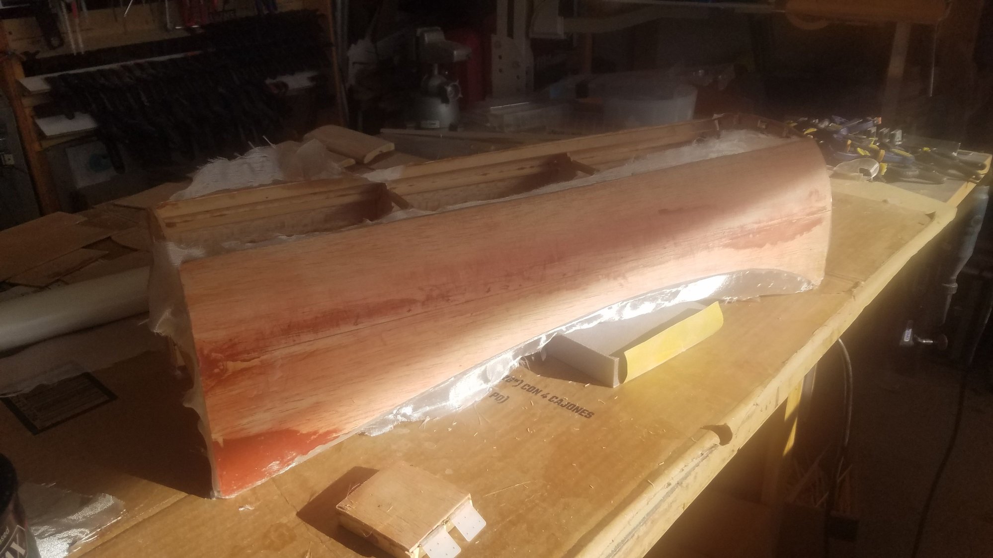
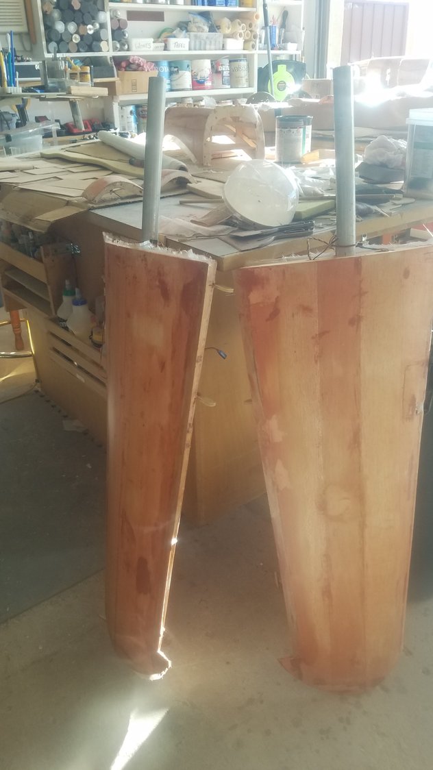
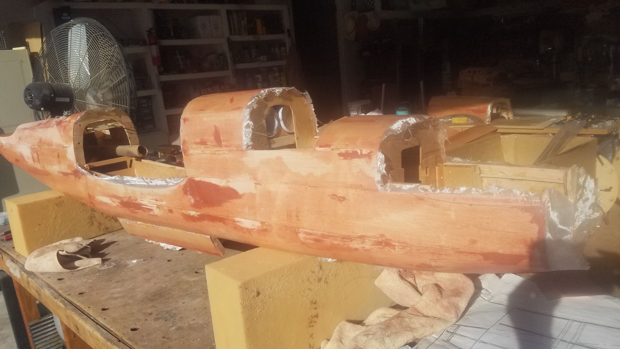
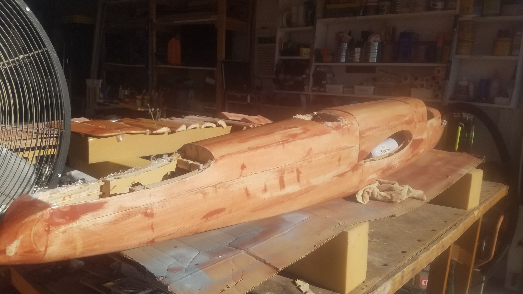
Fuselage center section with first poly application.
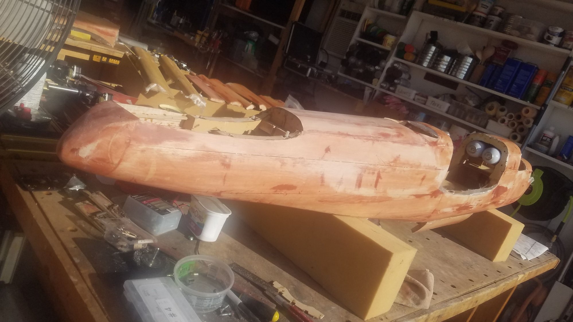
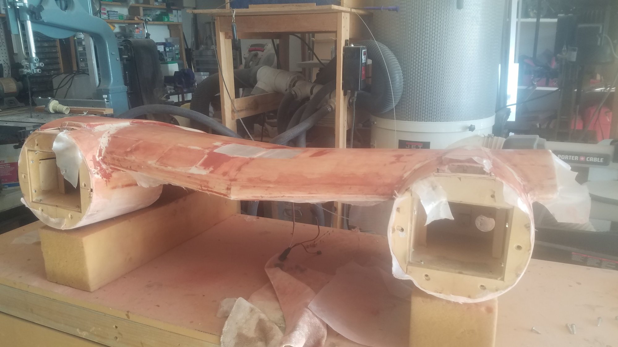
Fuselage about 60 % glass covered and will need many more coats.
I have already used one quart of the poly so far. However, it appears that the poly is very light weight compared to epoxy.
I am applying the 3/4 oz. fiberglass using Minwax polyacrylic and found that it is easier to work with than epoxy. It takes more coats, about 6, it is very easy to apply with a 3" foam brush and sands out very well. It's all a new experience but seems to be working well. Some say wait 2 hours and re-apply, I usually wait overnight which makes the surface much harder. Poly is much easier to apply than epoxy, just brush it on, with no smell and cleans up with water. As it is water based you have to coat the balsa with lacquer wood sealer first to keep the water in the poly from warping the wood. I did a quick sanding after the filler dried and then started the poly application. The photos show the progress so far and I will try and post as more work is done.
One thing that I am sure of is that you have to like to sand, and I haven't even gotten to the primer yet.
As I wait for the poly to dry on the other parts, I continue the filling of the low areas and fillets on the center nacelle. It will be the next section to get the poly applied. It will be a little tricky with all the curved surfaces, but I will try doing it in sections. I am not sure how it will handle the fillets.
Tail section will take some more work as the skin was sanded so thin that it just broke through when I picked it up. The bad area is on the other side and should be the last area to work on to finish the poly work. I will leave the vertical fins off and after finishing the poly will then glue them in place.
Wings with both sides glassed but will need more sanding and additional coats. The leading edge is double lapped so it should be somewhat stronger for possible hanger rash.
All hatch covers and small main gear doors covered and sanded. They will be the first parts to get sprayed with filler primer.
Flaps, ailerons, top hatch and the gear doors covered and will need one more sanding and more coats.
Poly coming up very smooth on finished parts.
Fuselage center section with first poly application.
Fuselage about 60 % glass covered and will need many more coats.
I have already used one quart of the poly so far. However, it appears that the poly is very light weight compared to epoxy.
03-29-2023, 10:30 PM
#150
Senior Member
Thread Starter
Getting all the parts and surfaces covered and multiple layers applied. Only getting several hours each day to work as family coming to stay a week but moving forward on getting the glass on the plane. Initial sanding with 120 - 180 grit, final sanding with 220 before filler primer sprayed on. If you have a sanding collection box, use it as it saves a lot of shop cleaning. Use of latex gloves and a mask really helps during this stage.

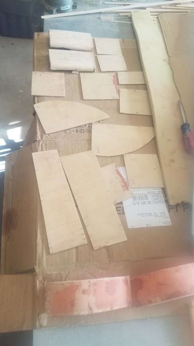
Parts to go.
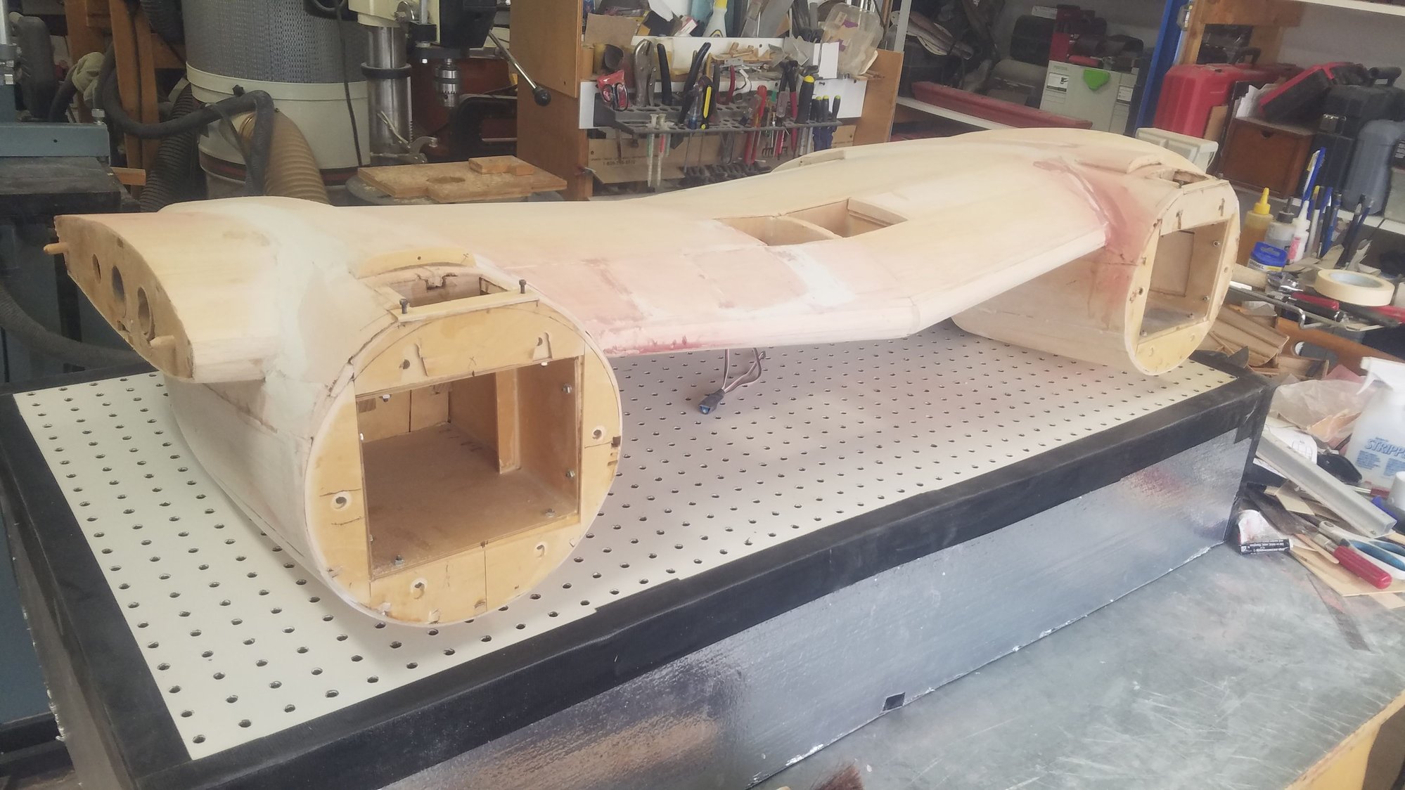
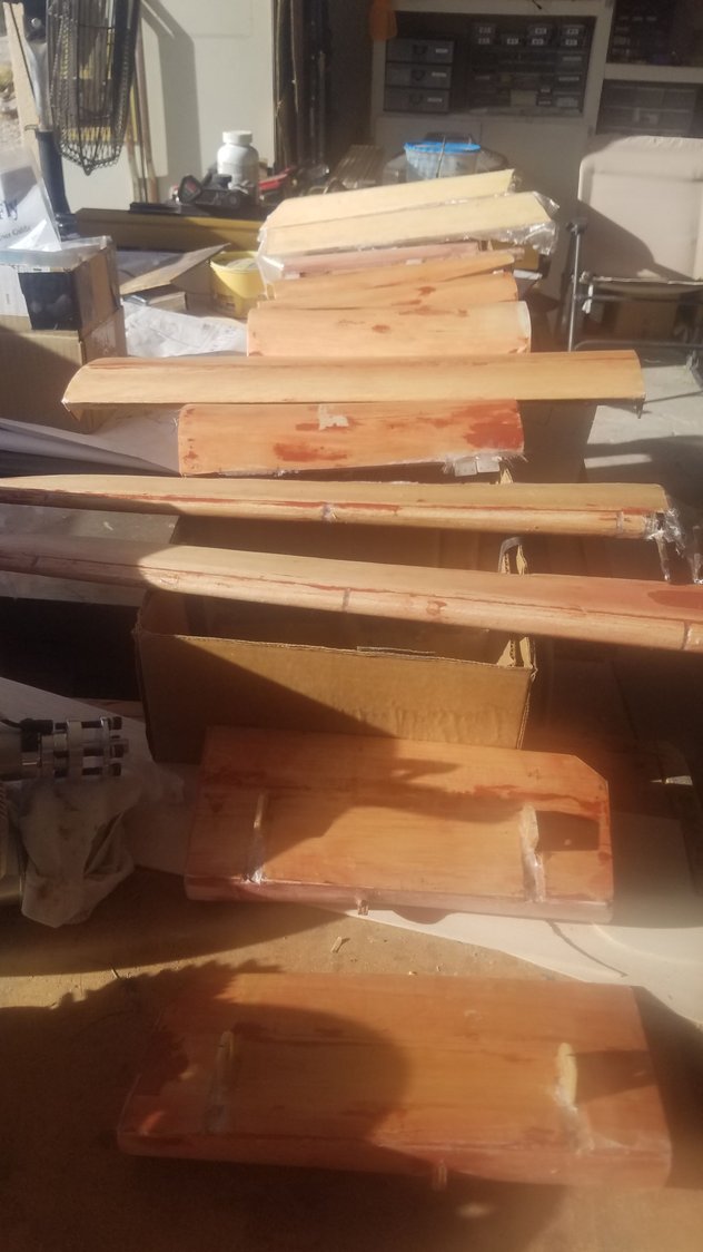
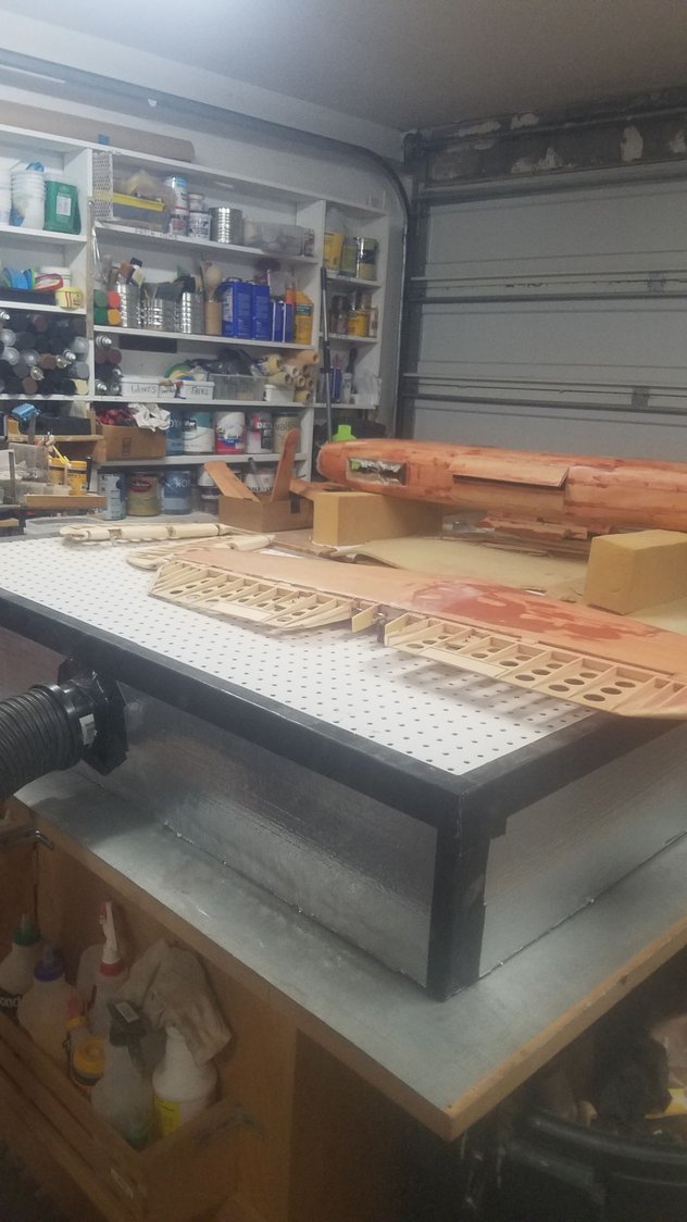
Starting the glassing of the center section
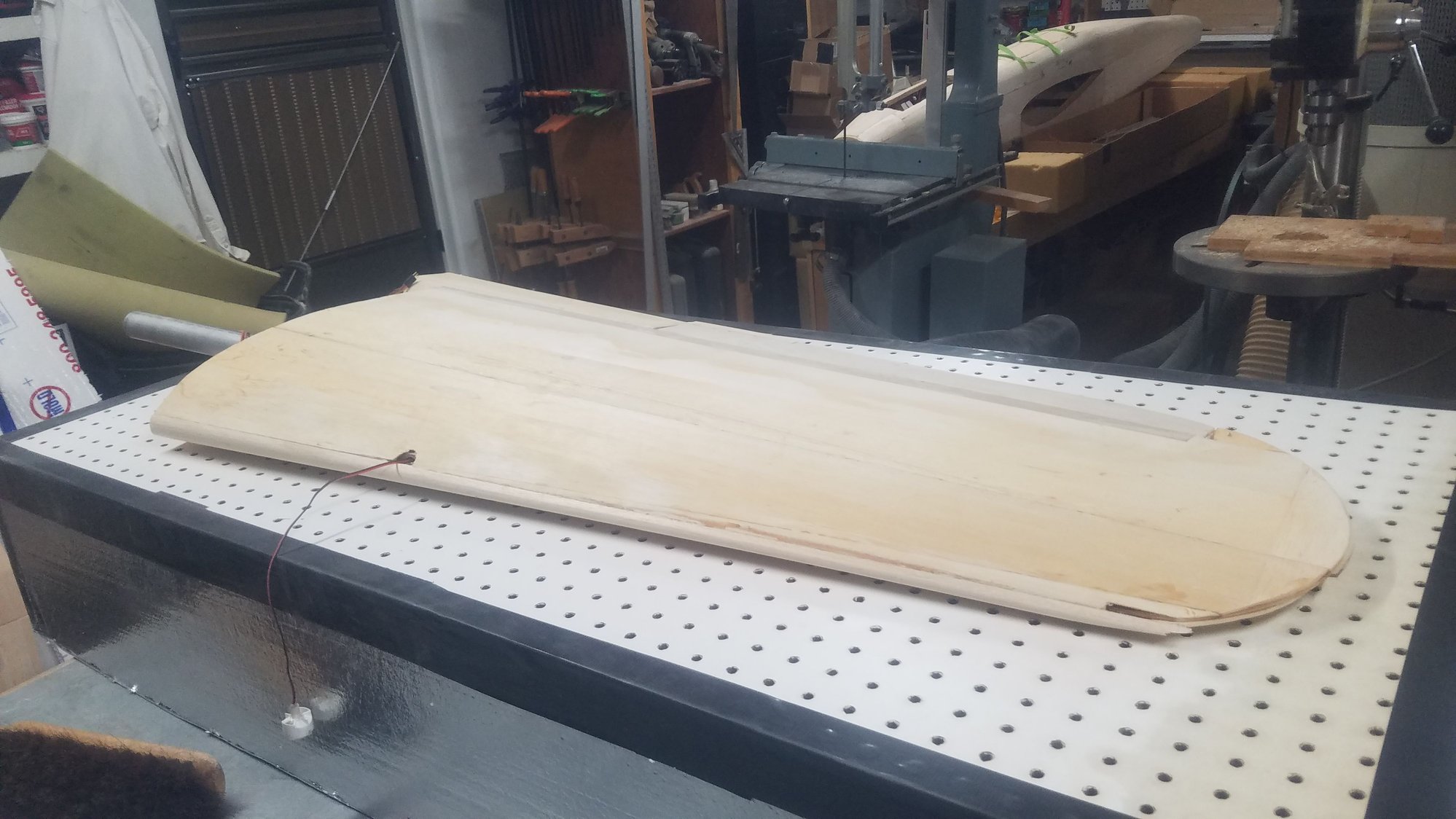
Just top side covered.
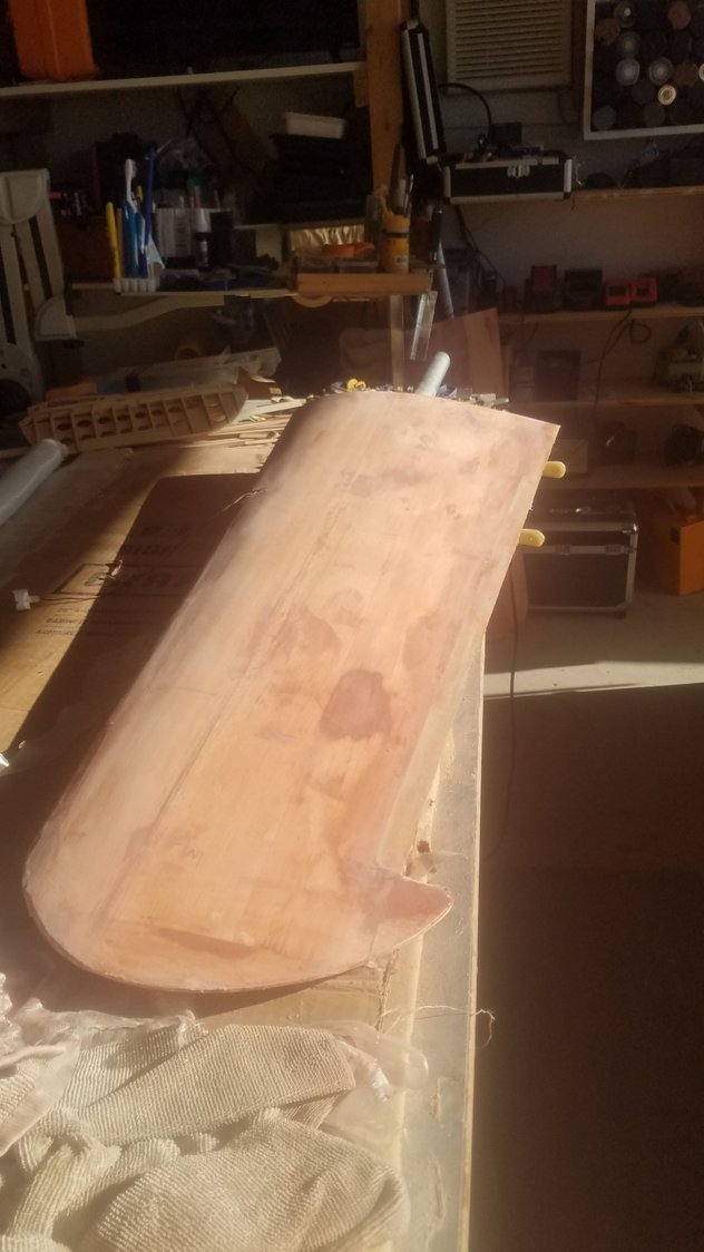
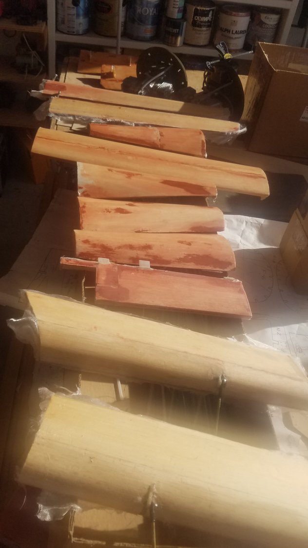
Wing with about 4 coats applied.
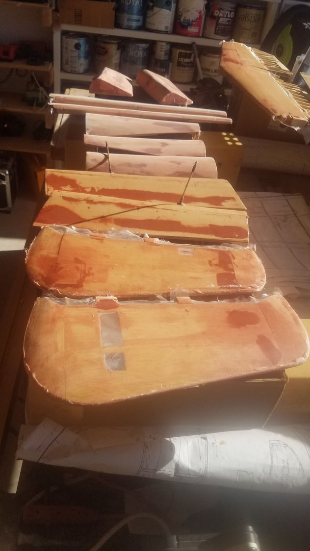
Most parts now with at least 3 coats and sanding to go.
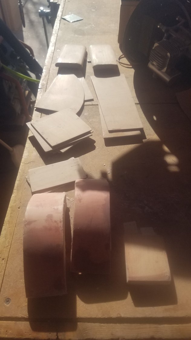
All these small parts have min. of 6 coats and are sanded out. Next step is filler primer.
Horizontal stab covered but some really low areas found on the top right side. 4 applications of glazing puddy to fill up the void and get it right. Leason here is do a better job of laying up the sheeting to start with. Low area is right here the bright light is shining.
Fuselage with 3 - 4 coats. Doing some sanding after each coat and that seems to help smooth the next coat.
After filling the shop with dust and puddy sanding dust, I spent several hours just vacuuming up the shop. I then got out my dust collector box to sand the remaining parts. The fuselage is sanded outside so as to reduce the dust in the shop. The sanding box made a huge difference, too bad I didn't think of it first. Best to wear a mask as well at this stage. There is a very large amount of dust created in this process.
These parts are pretty close to being finished.
I think I'll put one more coat on the wings. They look really good, but I will sand them one more time and give it a last coat.
Parts to go.
Starting the glassing of the center section
Just top side covered.
Wing with about 4 coats applied.
Most parts now with at least 3 coats and sanding to go.
All these small parts have min. of 6 coats and are sanded out. Next step is filler primer.
Horizontal stab covered but some really low areas found on the top right side. 4 applications of glazing puddy to fill up the void and get it right. Leason here is do a better job of laying up the sheeting to start with. Low area is right here the bright light is shining.
Fuselage with 3 - 4 coats. Doing some sanding after each coat and that seems to help smooth the next coat.
After filling the shop with dust and puddy sanding dust, I spent several hours just vacuuming up the shop. I then got out my dust collector box to sand the remaining parts. The fuselage is sanded outside so as to reduce the dust in the shop. The sanding box made a huge difference, too bad I didn't think of it first. Best to wear a mask as well at this stage. There is a very large amount of dust created in this process.
These parts are pretty close to being finished.
I think I'll put one more coat on the wings. They look really good, but I will sand them one more time and give it a last coat.