


Ziroli 1/7 (120") B-25 B scale build
 06-25-2022, 10:44 PM
#76
Senior Member
Thread Starter

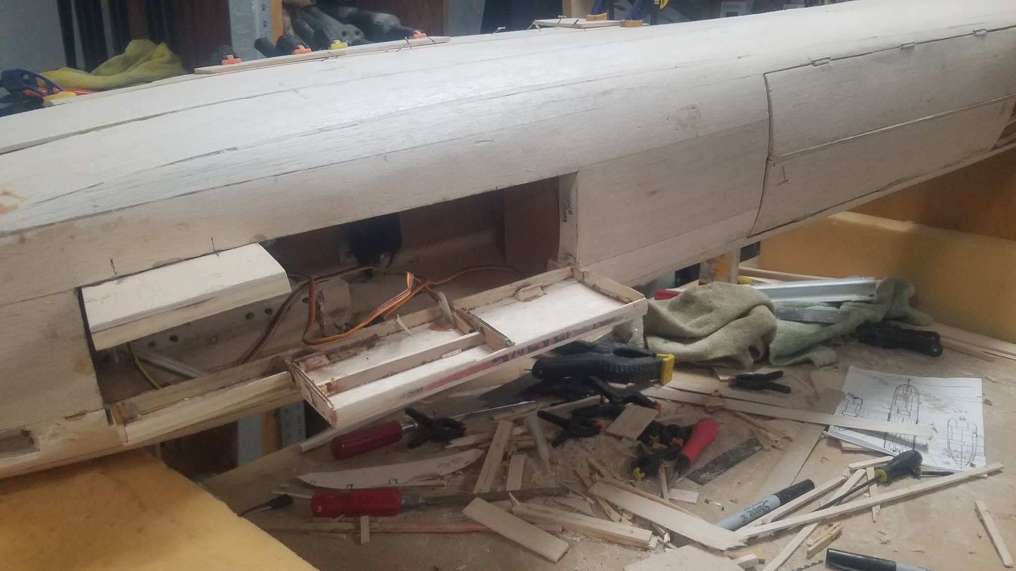
Servos and linkage installed on nose gear doors. Bomb bay doors installed and closed.
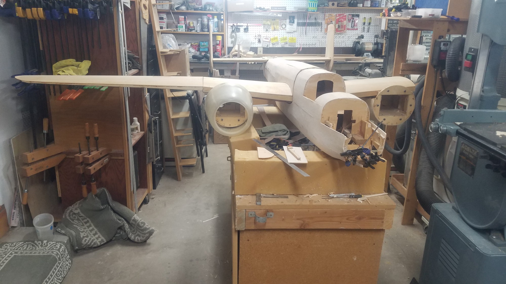
Just had to put it sort of together to see it. This is a big plane.

 06-25-2022, 11:04 PM
#78
Senior Member
Thread Starter
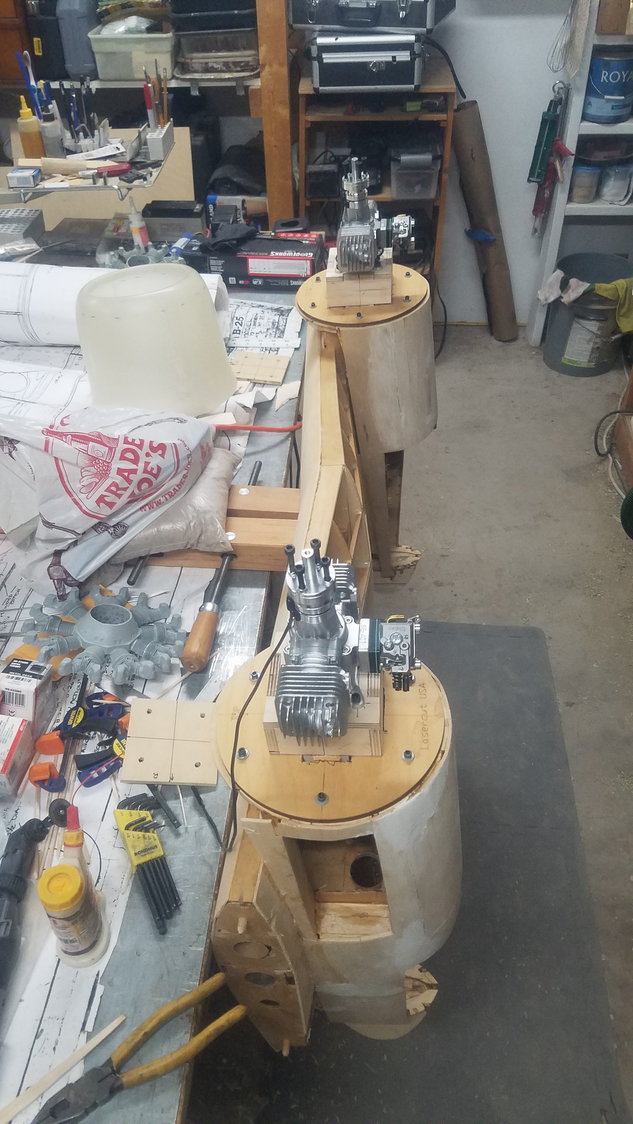
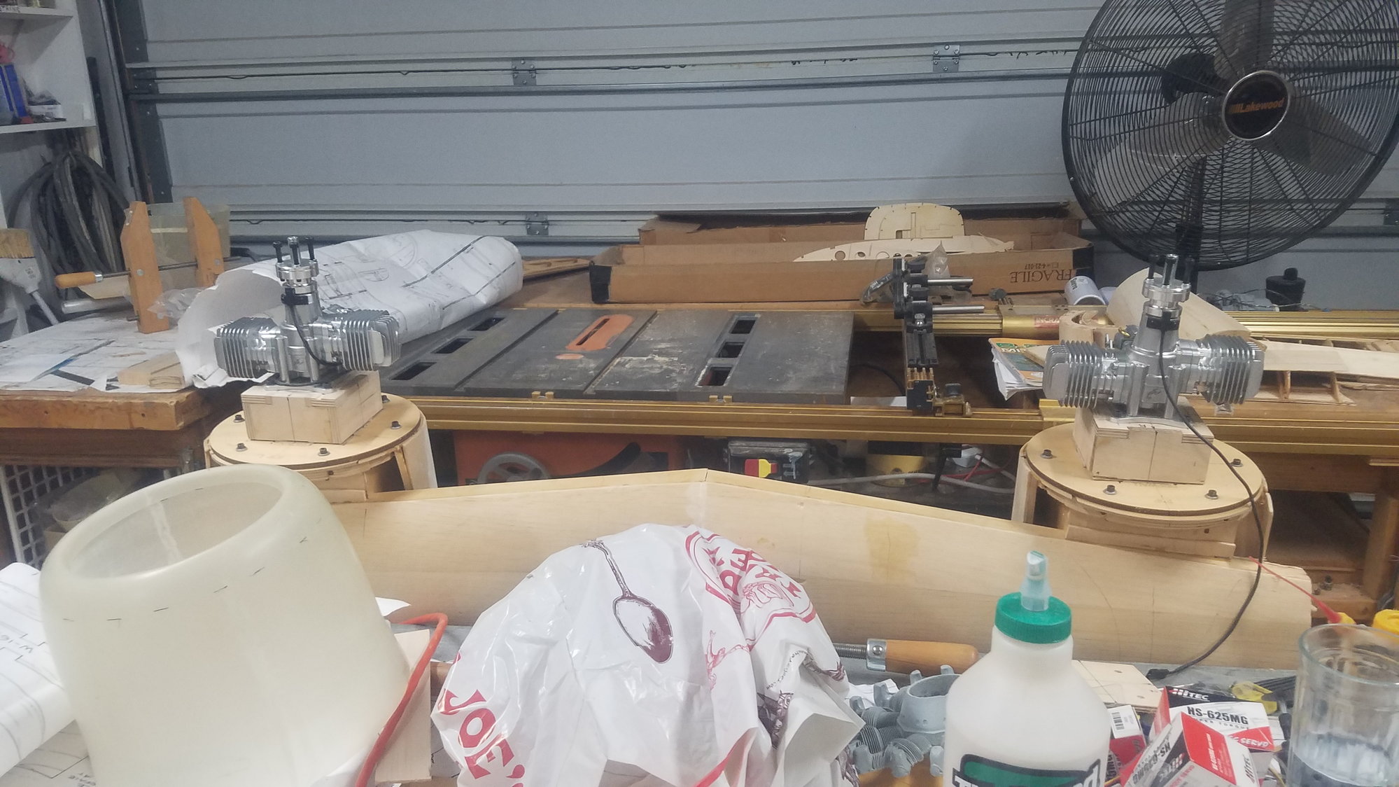
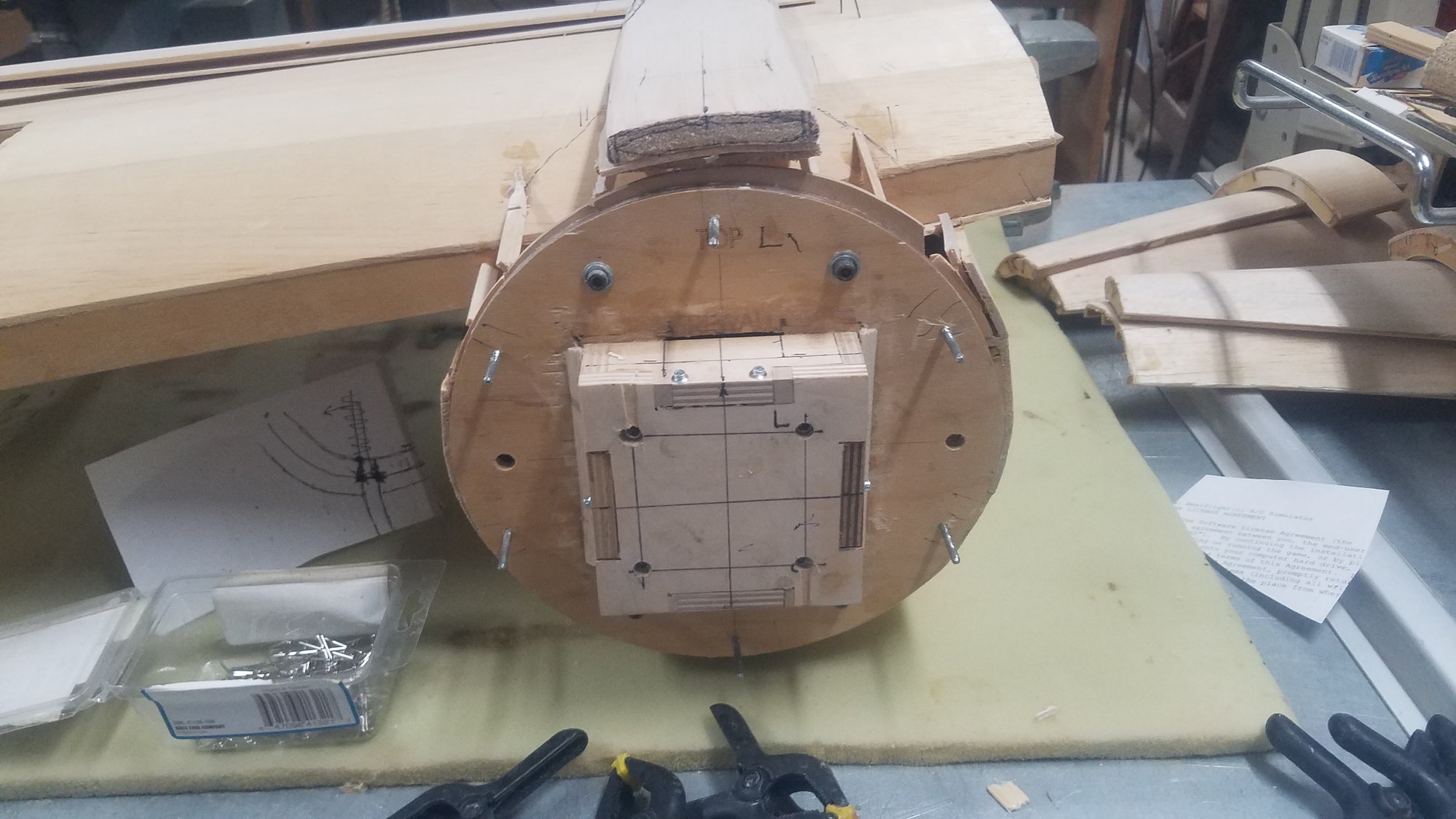
Mounting box structure, Right engine 3-degree right offset, left, no offset.
Cut through fire wall for added strength
Added gussets
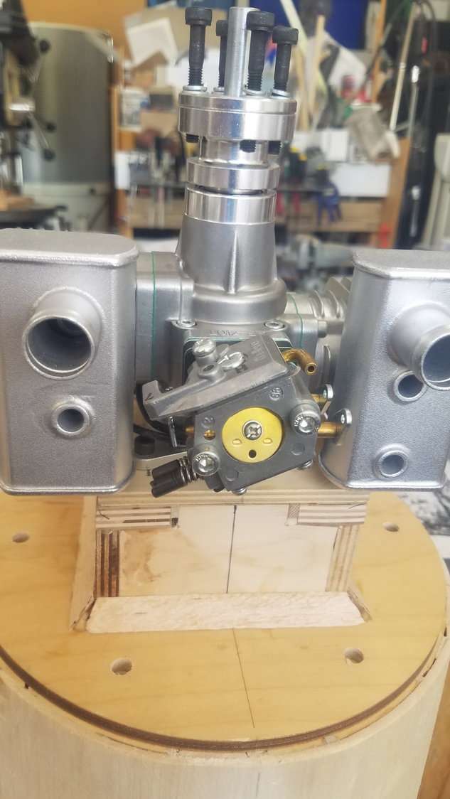
Problem as mufflers will not mount without altering spacer. Something is not right.
06-25-2022, 11:16 PM
#79
Senior Member
Thread Starter
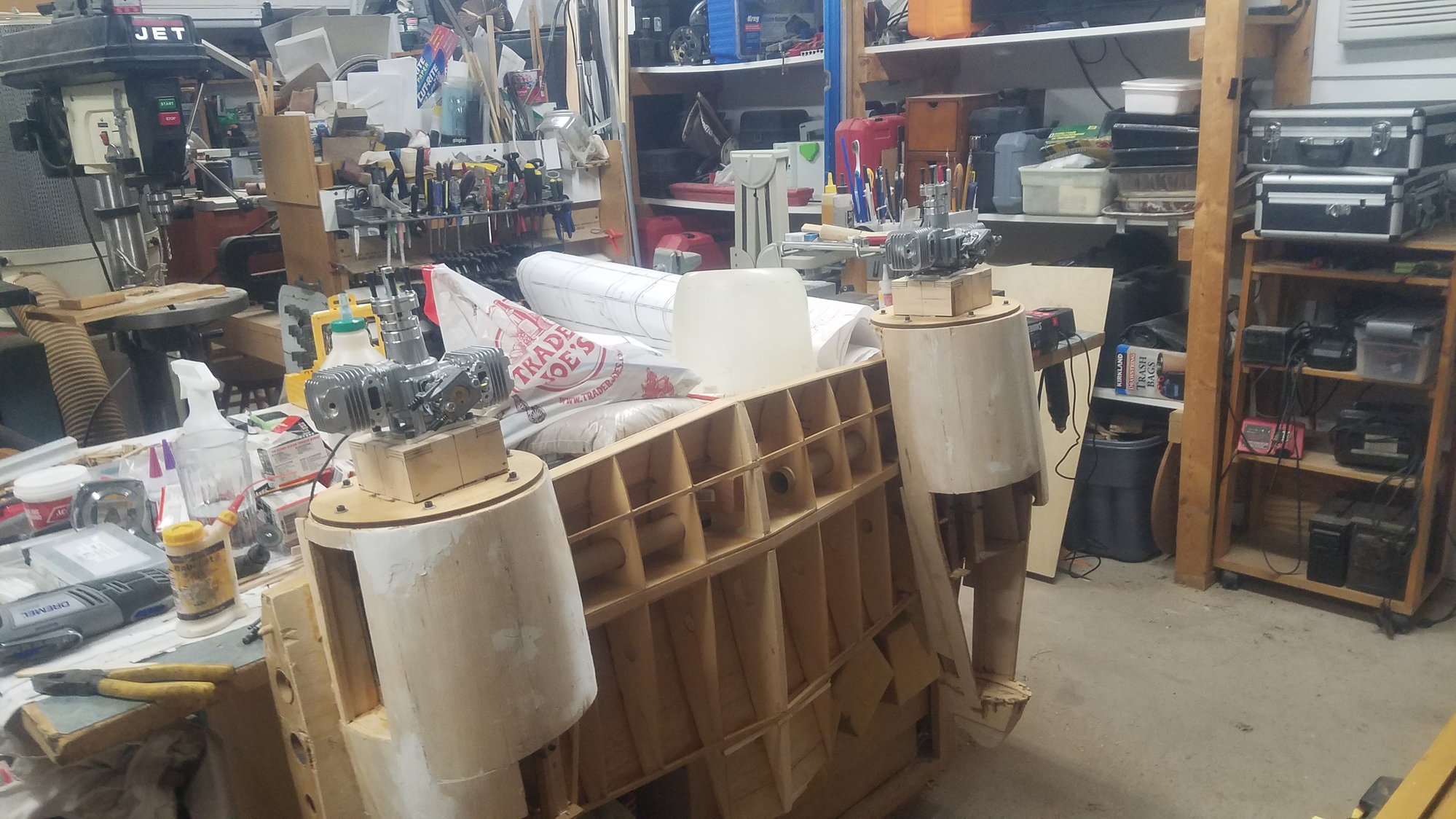
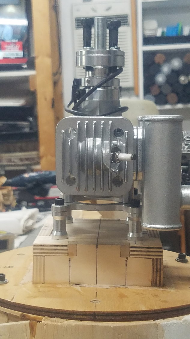
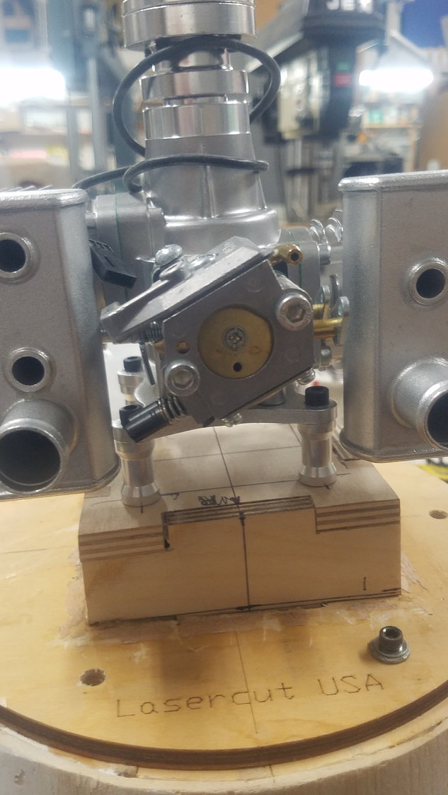
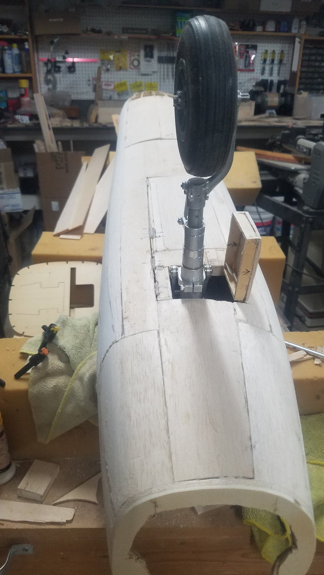
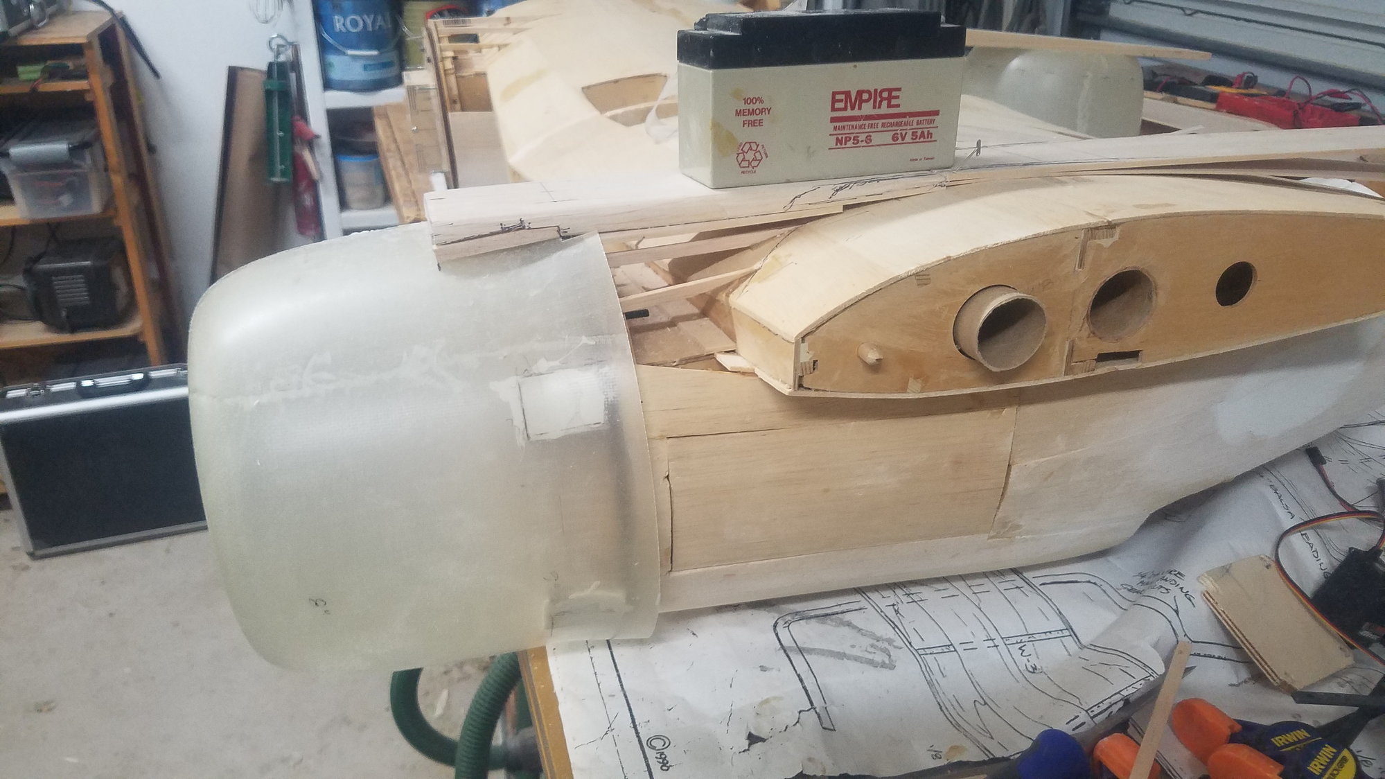
Took a 10-day RV trip out of town to just get away and relax and explore. Now back to work and found out the engines are designed to be mounted on their 7/8 " standoffs and are not to be mounted directly to box. I thought this direct mount would be better but found out that standoffs are needed for vibration. Now have to tear out mounting box and reduce it by 7/8" -- Ouch.
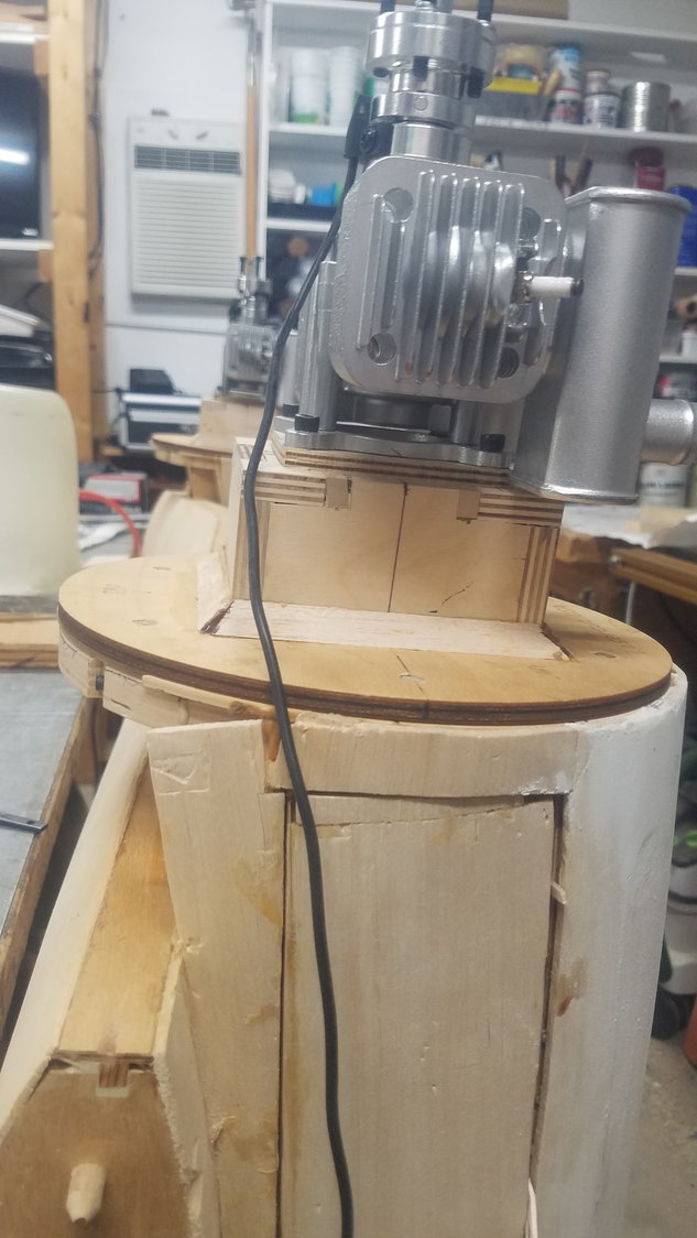
Mounted in error
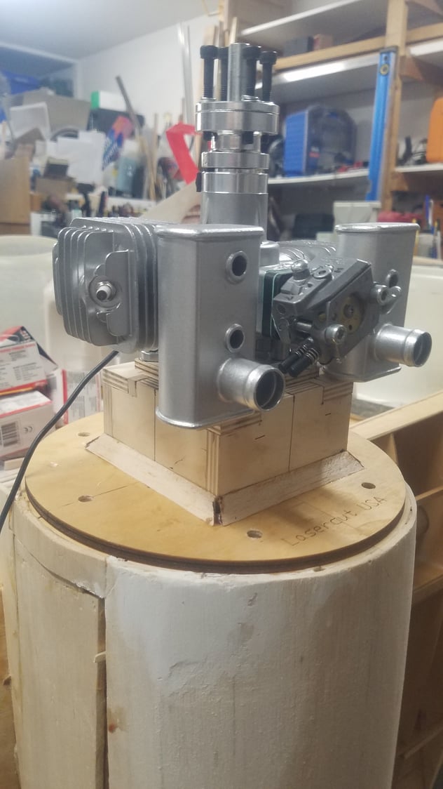
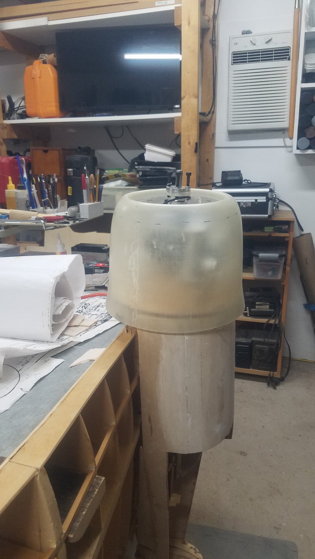
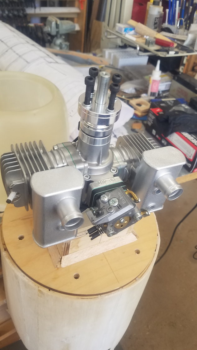
Cowl position is correct
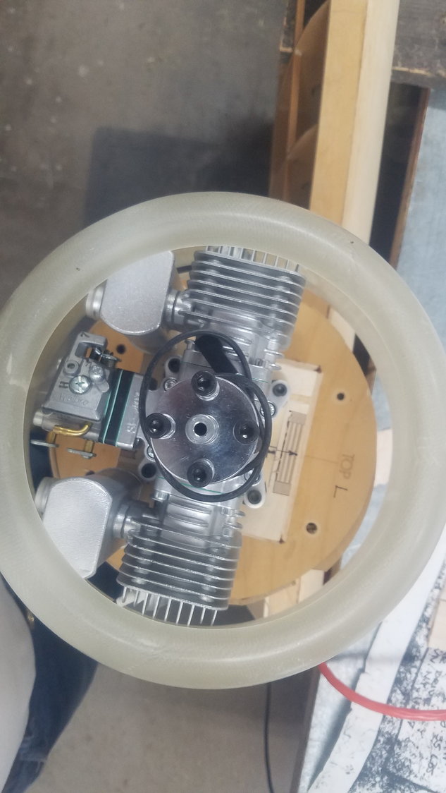
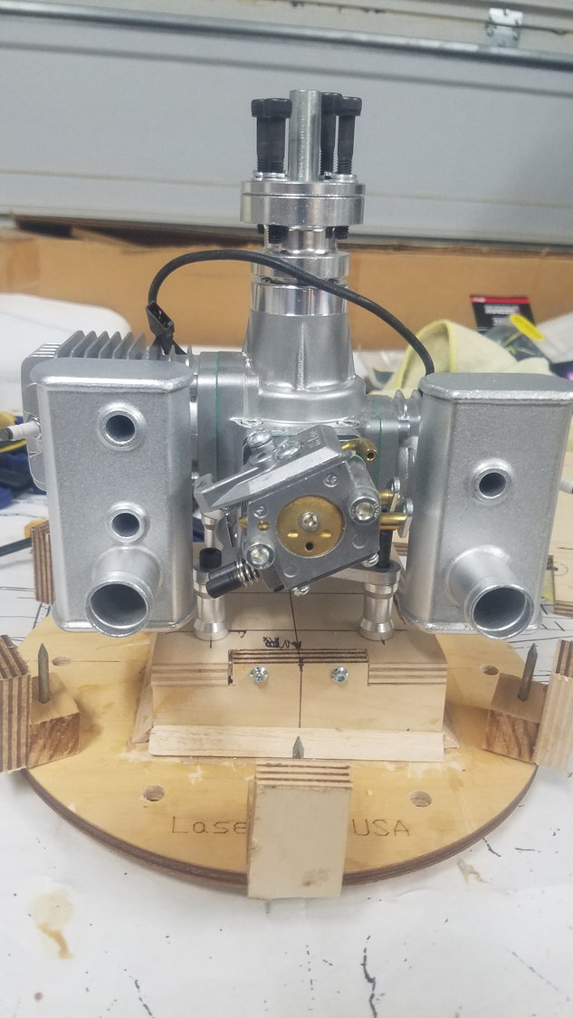
Engine is nice fit in the cowl.
Mounted in error
Cowl position is correct
Engine is nice fit in the cowl.
 06-25-2022, 11:34 PM
#81
Senior Member
Thread Starter
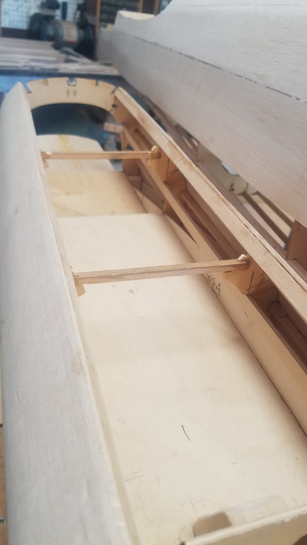
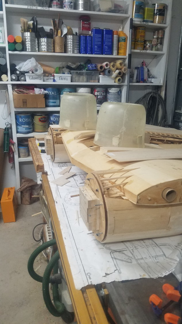
Floor and extra ply internal stringer added to strengthen the center section.
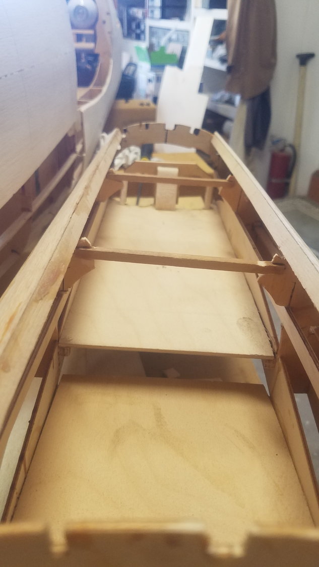
Retainer structure to hold air bottles in place added.
Formers doubled for blind nut installation.
06-26-2022, 12:02 AM
#82
Senior Member
Thread Starter
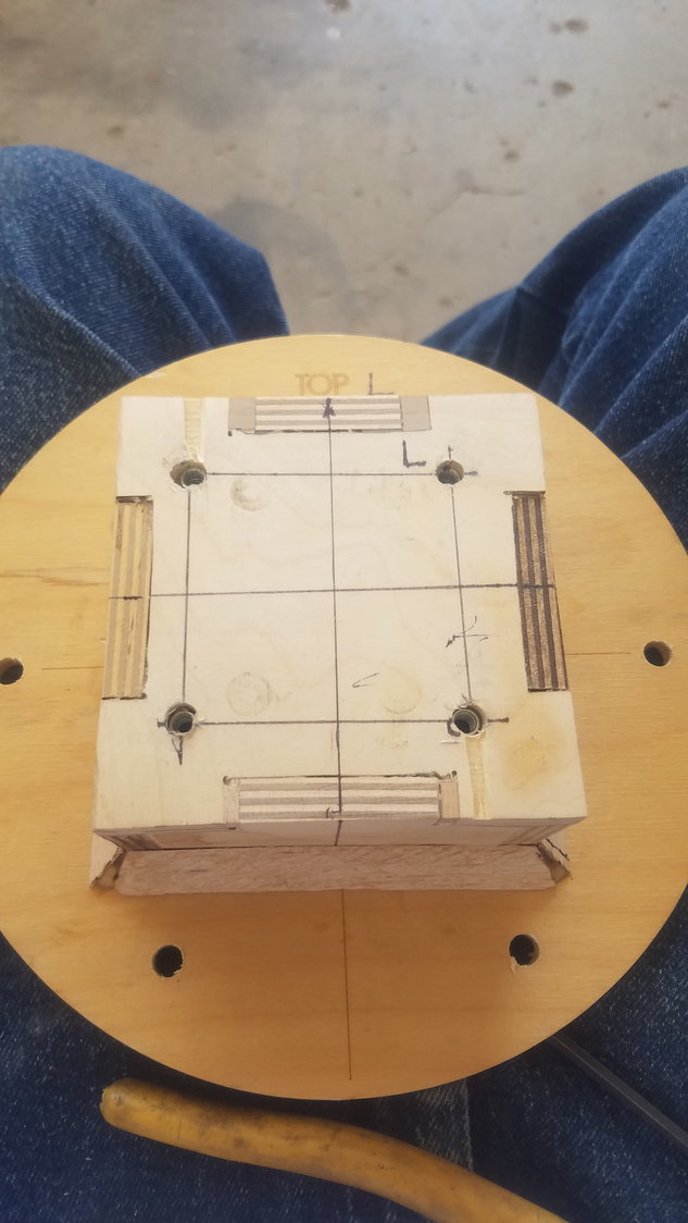
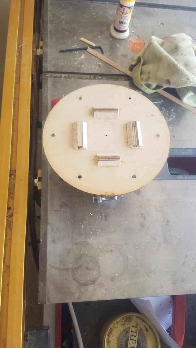
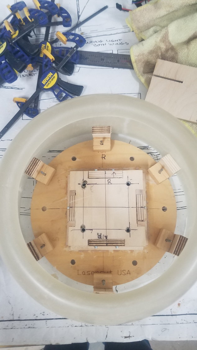
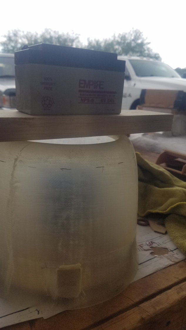
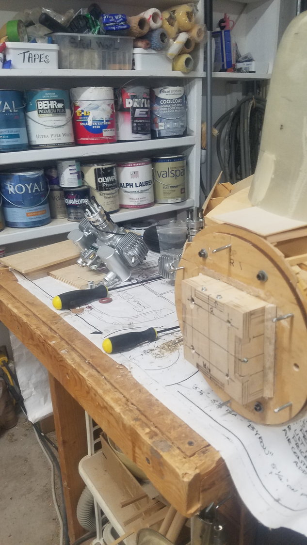
Finished mounting box by adding screws and gussets. I am using the round magnets and nail method to mount the cowl.
Wood mount for round magnets
1/2" magnets with nail size hole in wood mounting block
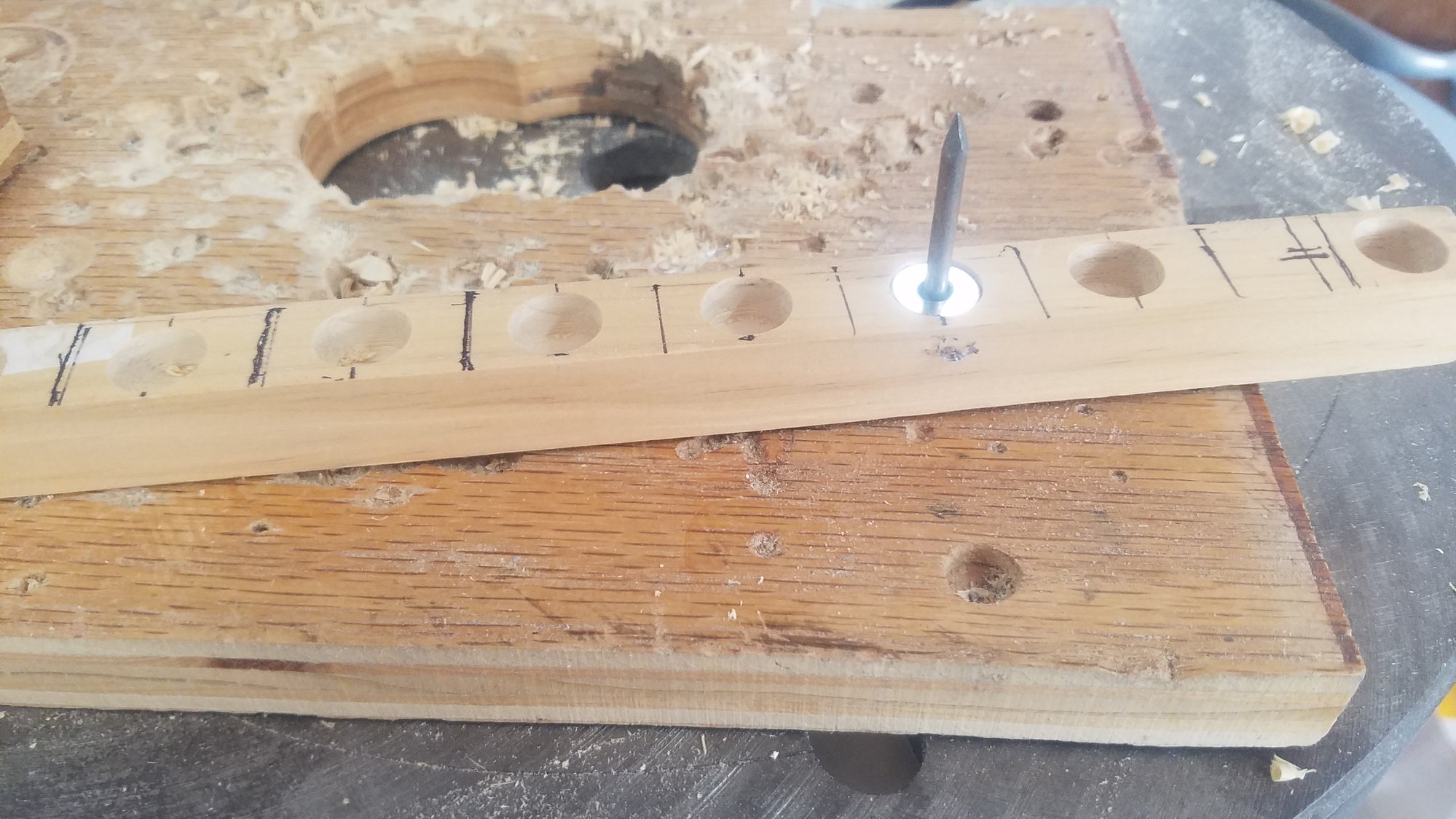
Example of nail and magnet
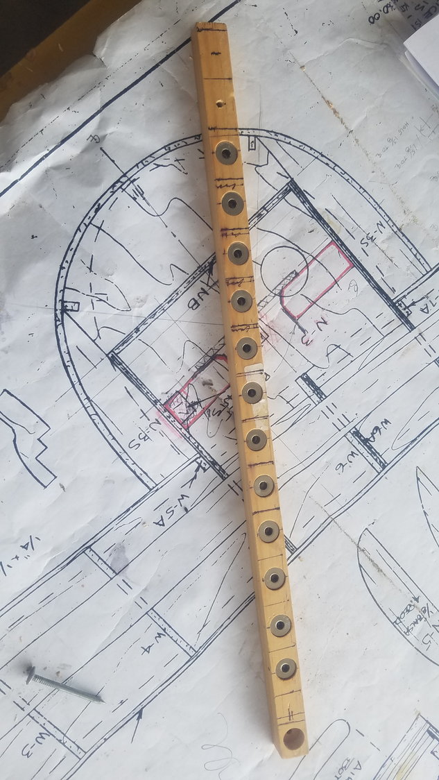
All magnets glued in
Screws and gussets installed

Magnet mounting blocks built, used 1/2" spacing on cowl. Should be good air flow over engine.
Cowl dry fit, all looks good.
Vertical view showing spacing.
Tomorrow will glue in mounding blocks to cowl
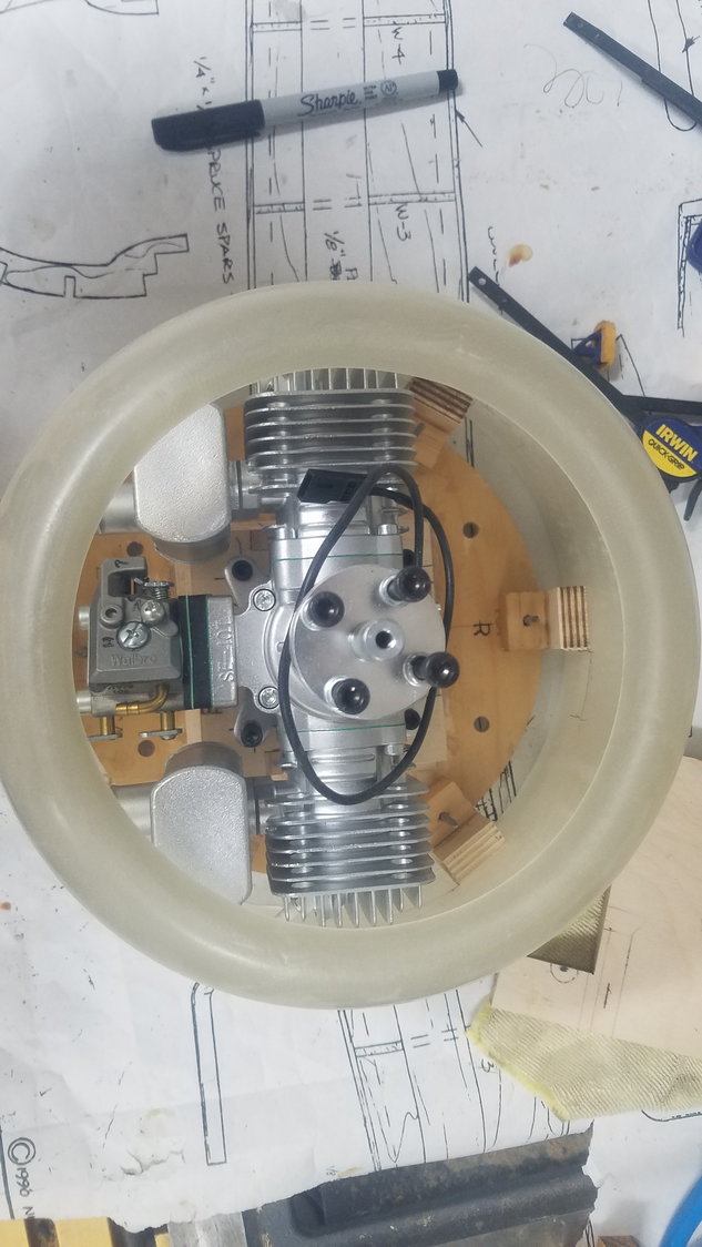
Engine and cowl blocks. Could need some modification to get blocks to clear engine to remove cowl.
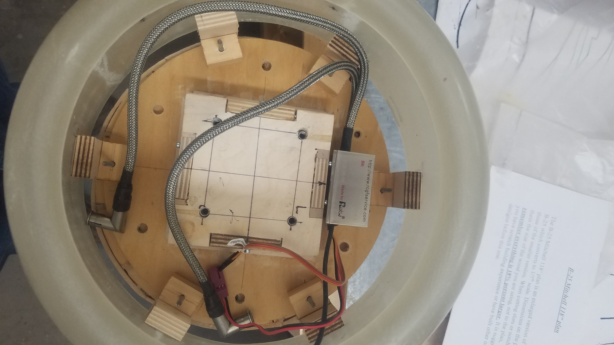
Ignition module location, dry fit.
Wood mount for round magnets
1/2" magnets with nail size hole in wood mounting block
Example of nail and magnet
All magnets glued in
Screws and gussets installed
Magnet mounting blocks built, used 1/2" spacing on cowl. Should be good air flow over engine.
Cowl dry fit, all looks good.
Vertical view showing spacing.
Tomorrow will glue in mounding blocks to cowl
Engine and cowl blocks. Could need some modification to get blocks to clear engine to remove cowl.
Ignition module location, dry fit.
06-26-2022, 08:43 AM
#83
Senior Member
Thread Starter
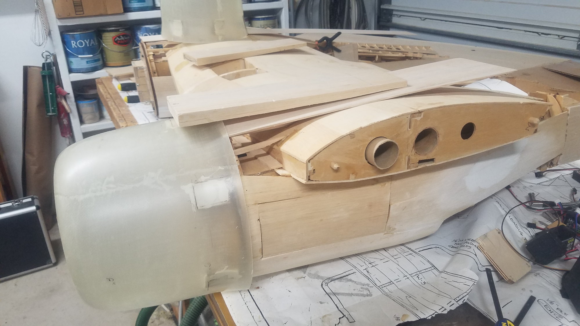
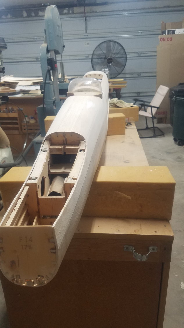
Photos of finished nose skinning, location of air tank's, center section bolts, internal stringer and air tank restraint, gluing of cowls.
Mistake discovered!!
After working in the morning on the cowls, we had a lunch date with friends and after I returned, I flipped the fuselage over and saw that I have mounted the nose gear doors on the wrong side. I never flipped the image over in my mind with looking at a scale drawing of the underside of the plane. Have removed the doors and have reworked the arrangement to be correct. Will try and rehinge tomorrow. Sure am glad I discovered this now rather than much later. Add this mistake to the thousands I have made.
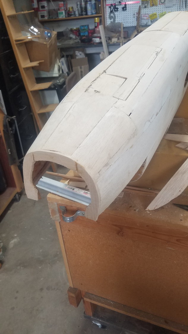
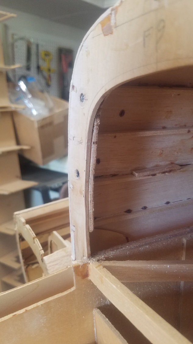
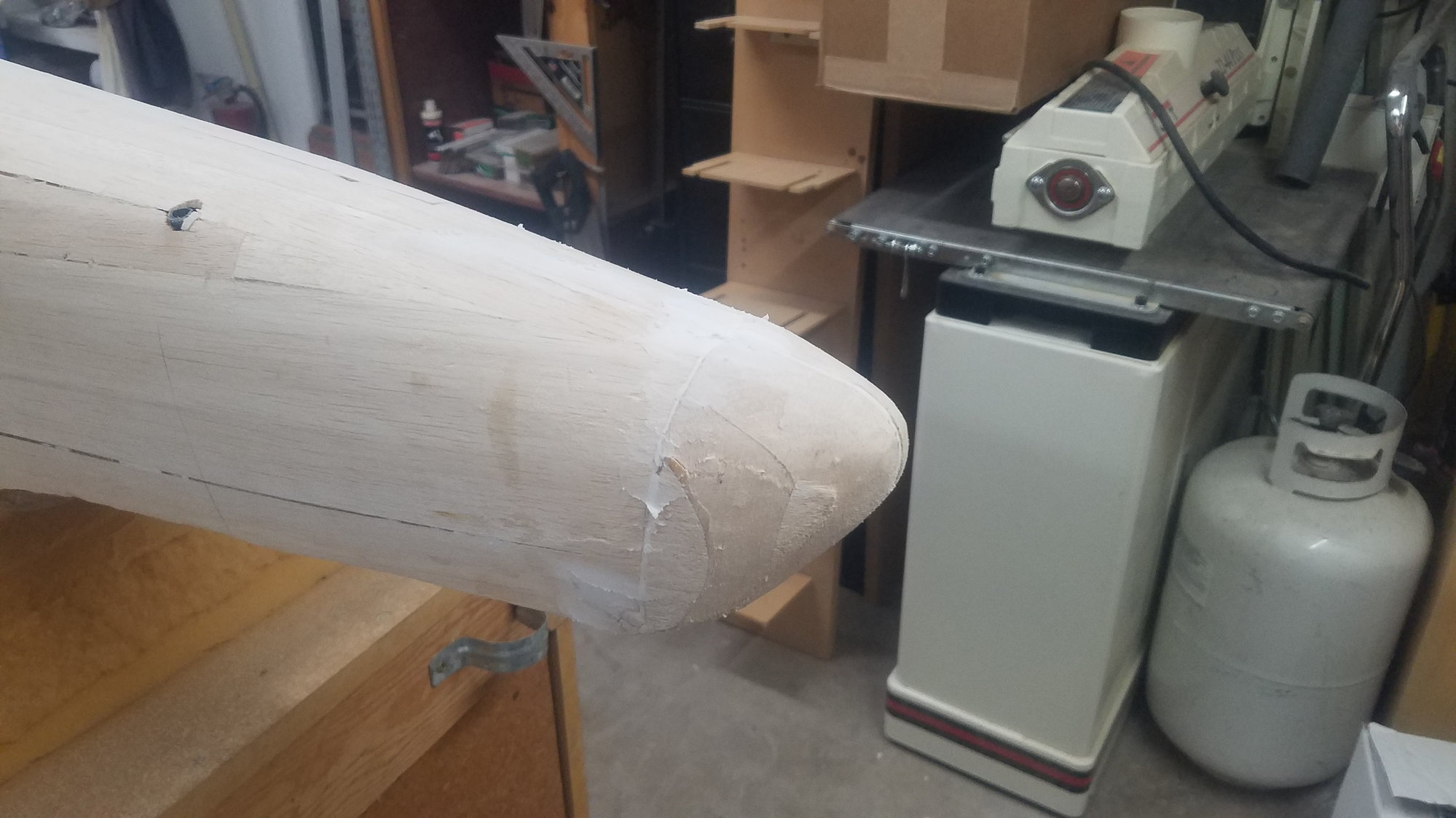
Nose skinning completed
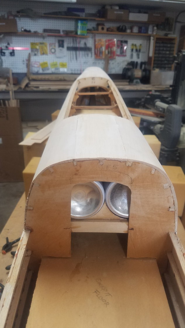
Location of air tanks. Keeping everything as far forward as possible.
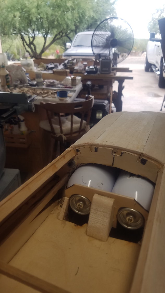
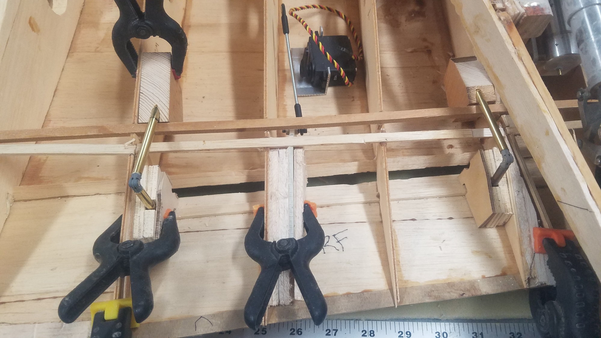
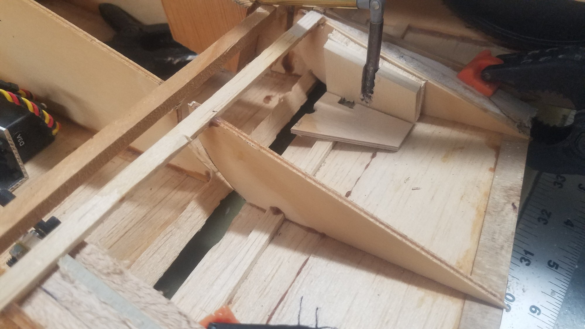
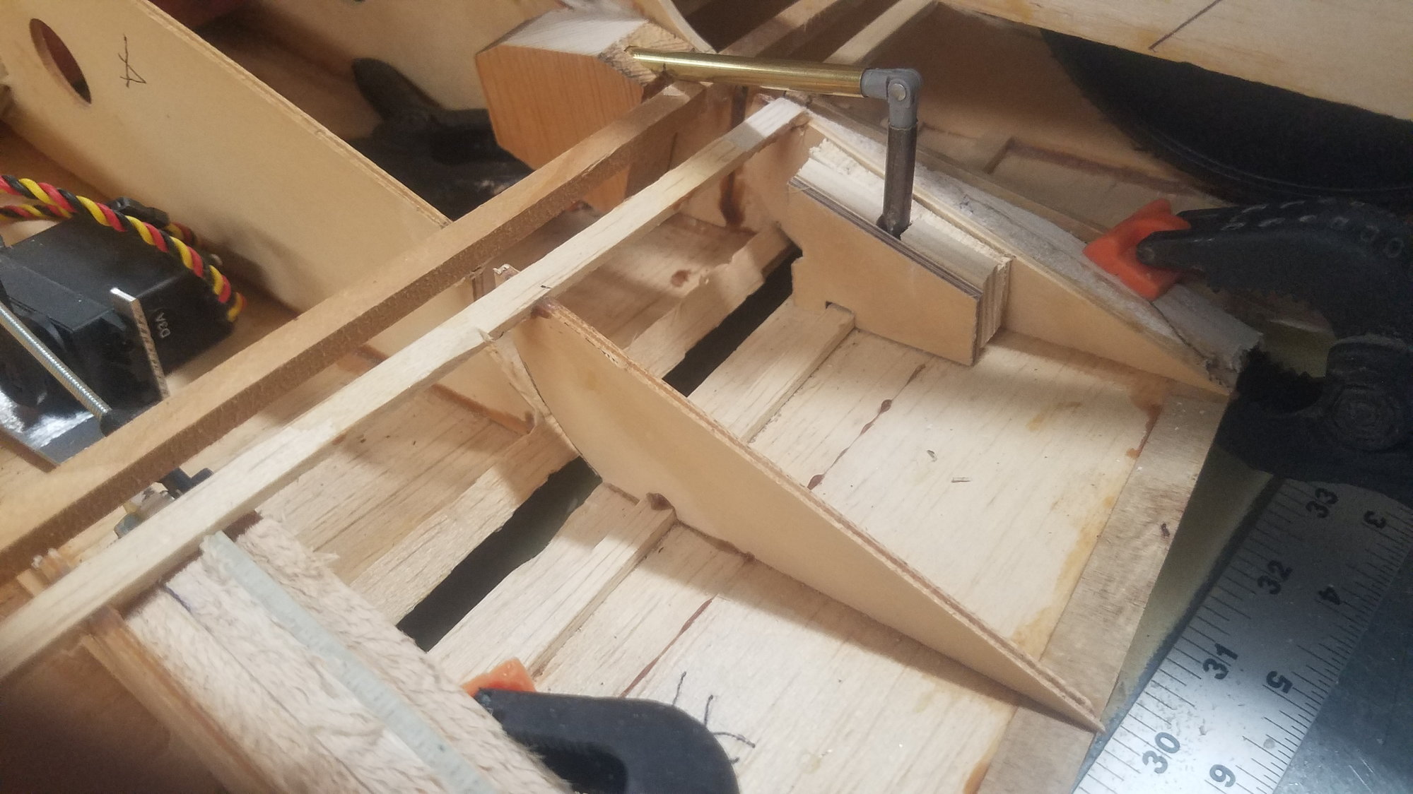
Center section restraint for air tanks.
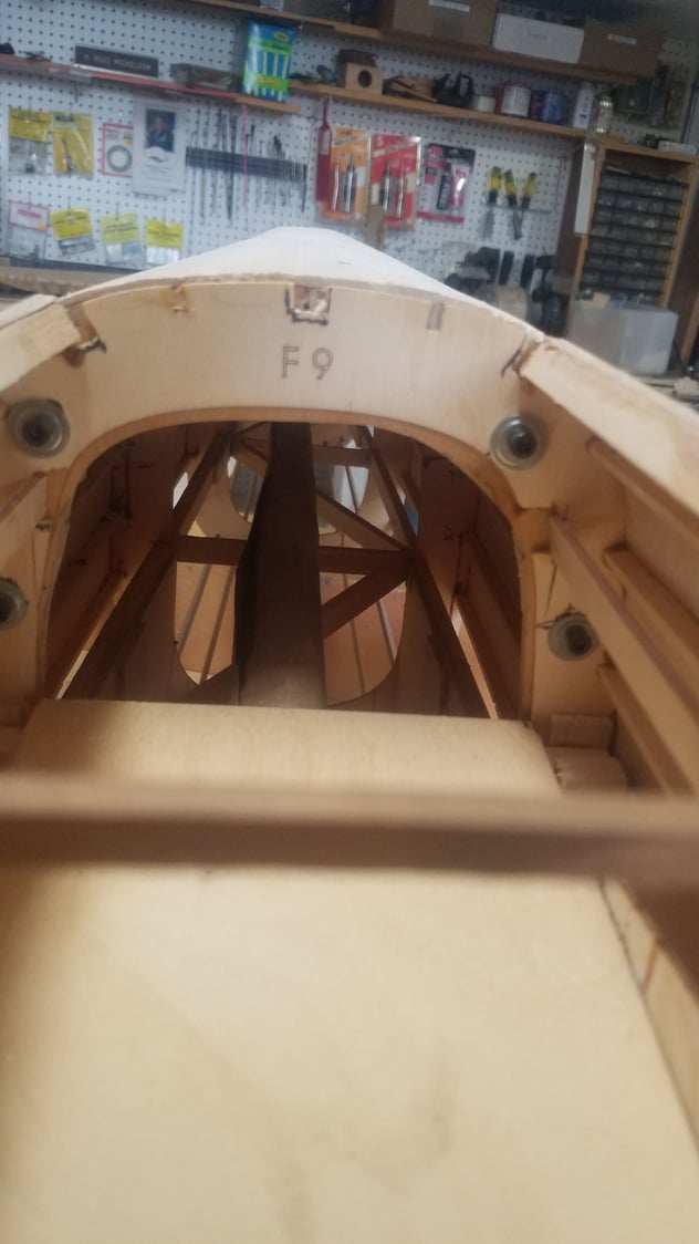
Rear bolt pattern for center section. Four bolts on front of center section as well.
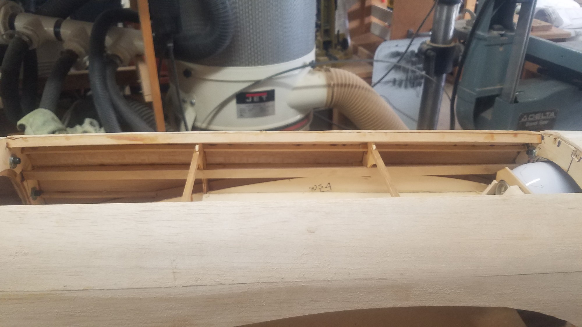
Better view of internal stringer
Drilled holes for Aeropoxy to get a better connection.
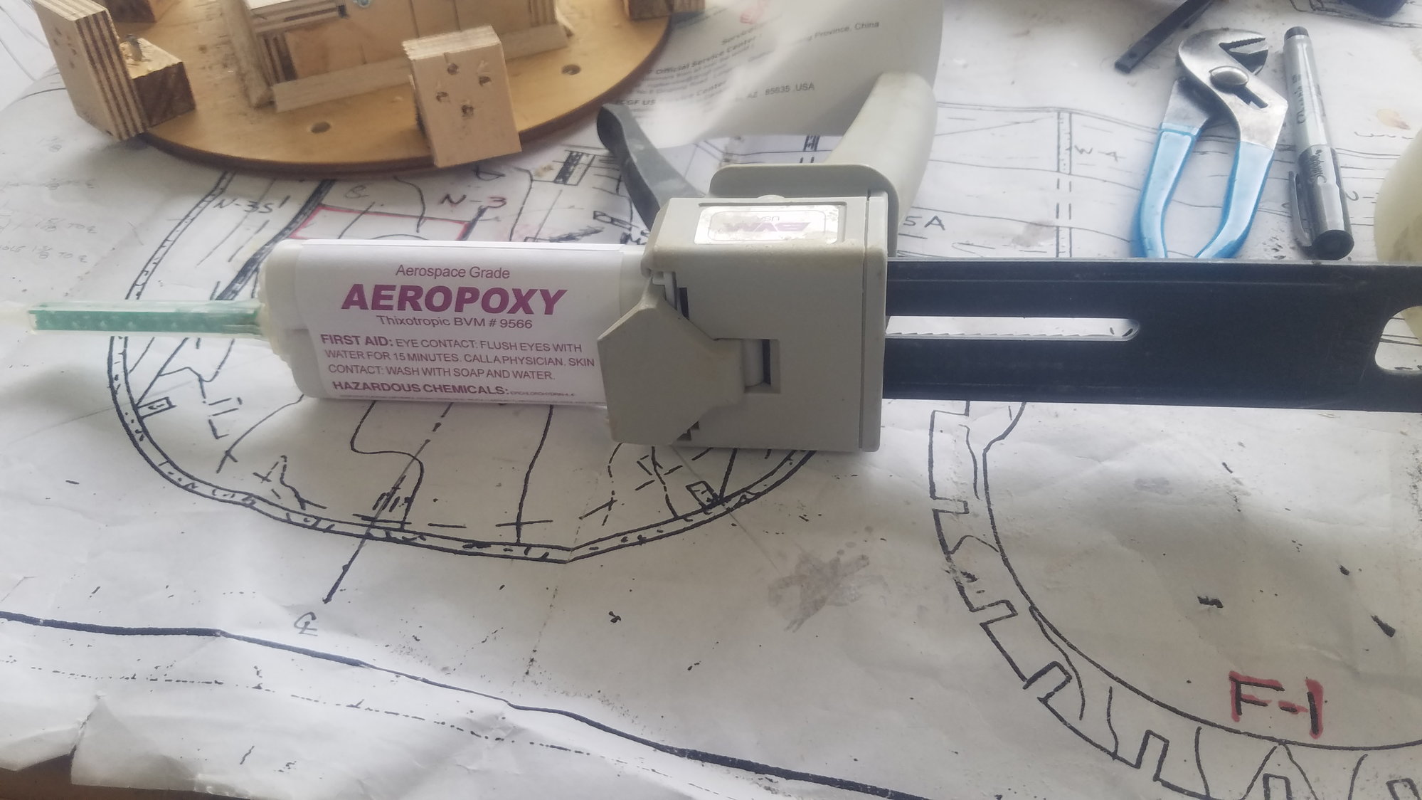
Aeropoxy tool, cartage, tip. I reuse tip by cleaning in Acetone and compressed air.
Cowl gluing up
Mistake discovered!!
After working in the morning on the cowls, we had a lunch date with friends and after I returned, I flipped the fuselage over and saw that I have mounted the nose gear doors on the wrong side. I never flipped the image over in my mind with looking at a scale drawing of the underside of the plane. Have removed the doors and have reworked the arrangement to be correct. Will try and rehinge tomorrow. Sure am glad I discovered this now rather than much later. Add this mistake to the thousands I have made.
Nose skinning completed
Location of air tanks. Keeping everything as far forward as possible.
Center section restraint for air tanks.
Rear bolt pattern for center section. Four bolts on front of center section as well.
Better view of internal stringer
Drilled holes for Aeropoxy to get a better connection.
Aeropoxy tool, cartage, tip. I reuse tip by cleaning in Acetone and compressed air.
Cowl gluing up
Last edited by rossmick; 06-26-2022 at 05:19 PM. Reason: Additional information
06-27-2022, 05:58 PM
#84
Senior Member
Thread Starter
Nose gear doors are now on the correct side. Follower door is not scale but enlarged due to gear.
Build up on nacelles for air intake. Oversized cowl makes this a little tricky.
Trying to figure out how this will work. Thinking of notching out a section of the cowl ??
Magnet/nail cowl attachment works very well. Can barely get them off. Cleaned up nails and it helped in removing the cowl.
 06-30-2022, 05:51 PM
#86
Senior Member
Thread Starter
Closing up fuselage. i have paper tube installed to pass through the servo and lighting wire for the tail.
First air intake concept - needs work.

Reworking botched first install of skin on nacelles. 2nd air intake started and ruffed in.
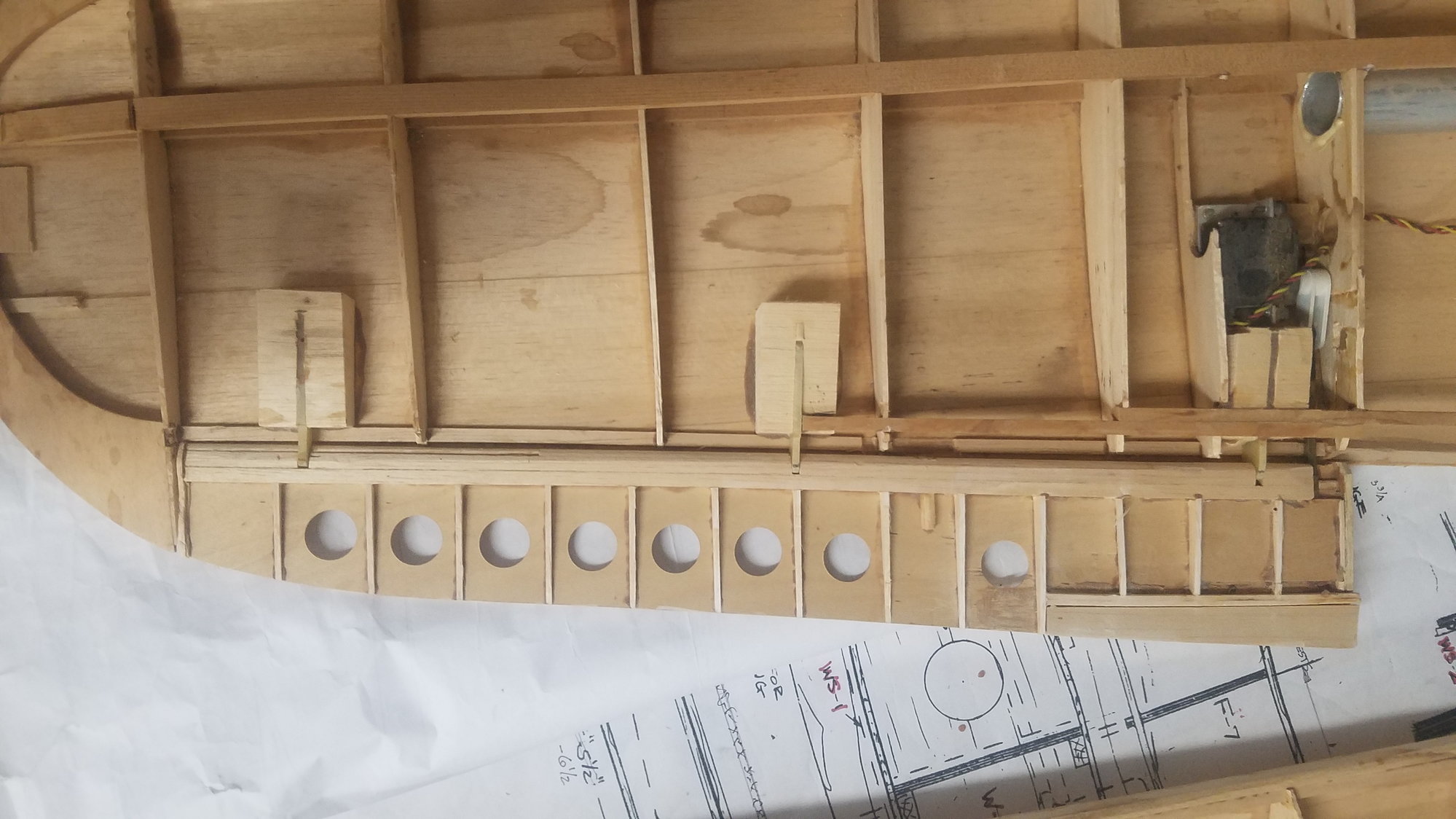
Build up 1/4" ribs for flaps to be used for hinges and servo connection.
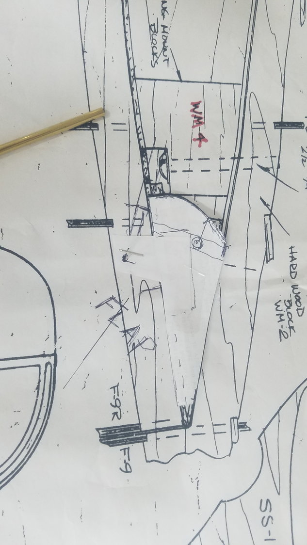
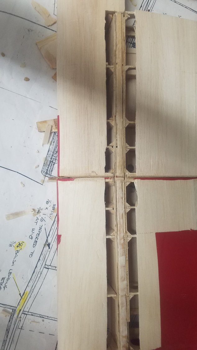
Determining the hinge point for the semi fowler flap. My reading is that the hinge point is under the farthest wing cover trailing edge of flap cover. As drawn out this location is very similar to the actual flap hinge point in the full-size plane.
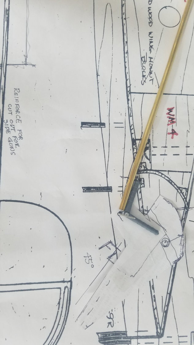
To reach this location the hinge will need an extension. Robart hinge fits perfectly in the brass tube. Will use the brass extension on both ends of the hinge.
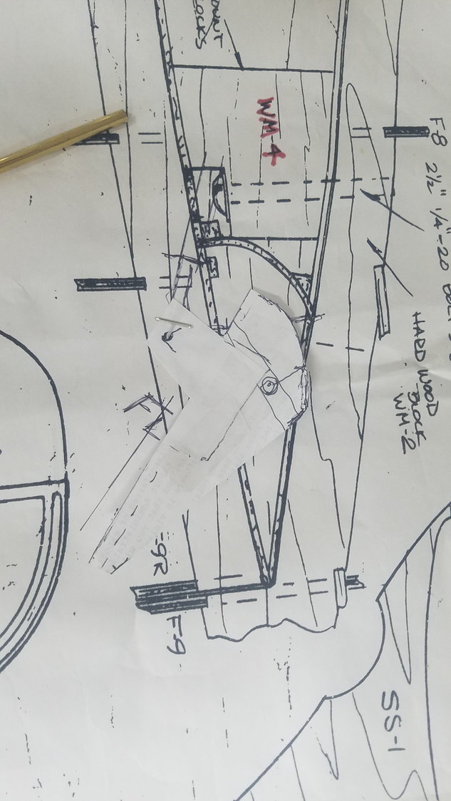
Flap rotated 45 degrees and you can see the air channel that is created for the air to pass over the flap when extended.
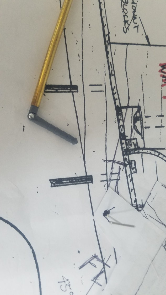
Shows hinge in brass tube.
Fixed broken tail section of center section.
Will sand in solid section used to keep the skin from breaking out.
07-01-2022, 04:33 PM
#87
Senior Member
Thread Starter
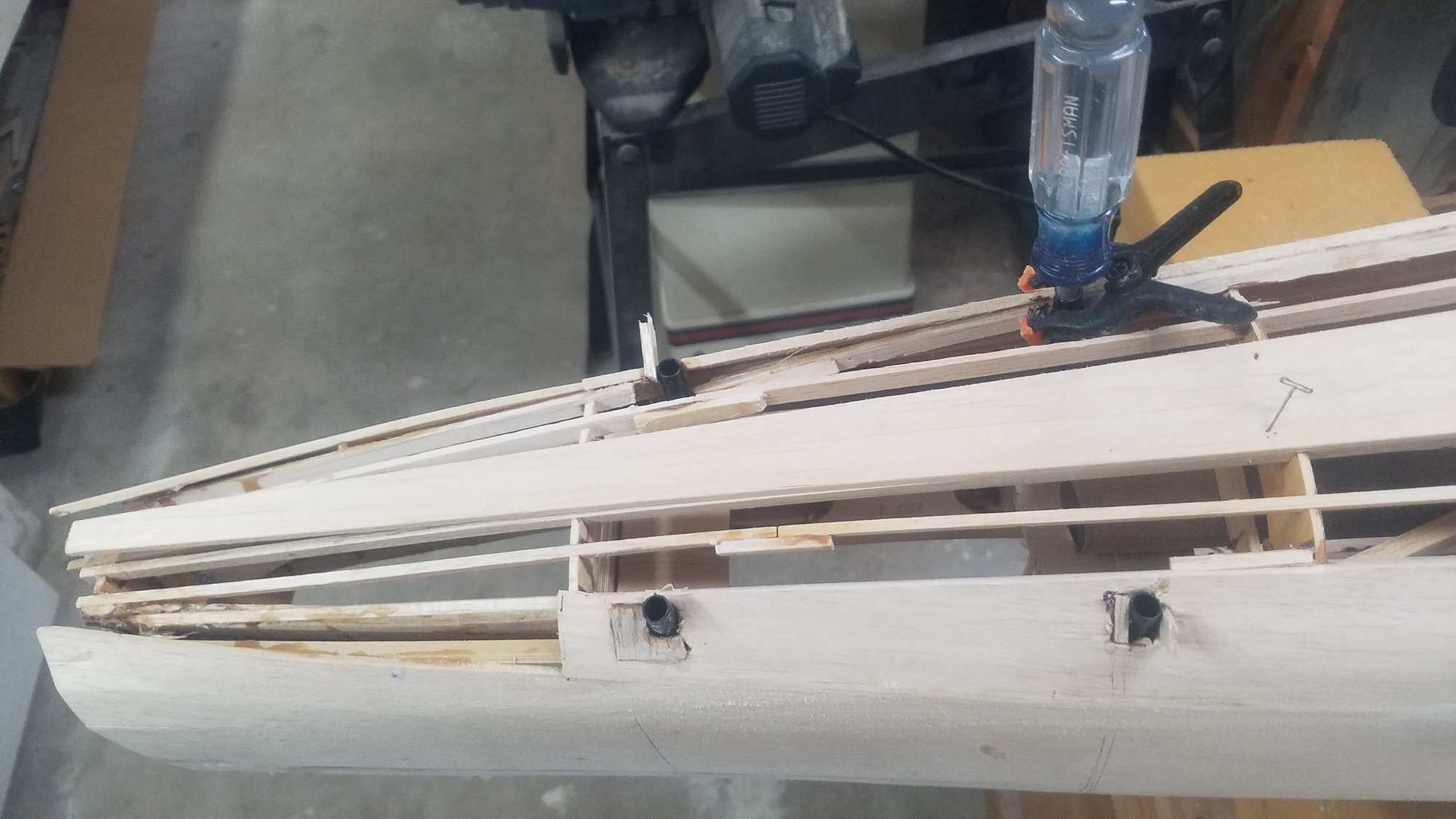
Continuing to skin fuselage. Feed tubes are installed to access the hold down bolts that attach the tail section. There is a lot of piecing going on here to go around the bottom of the fuselage, slow but sure.
Skinning front of nacelle. Will apply another layer, however this thin layer should feather into the wing much better than the 1/8"
Last edited by rossmick; 07-01-2022 at 04:42 PM. Reason: Add text
07-03-2022, 08:31 PM
#88
Senior Member
Thread Starter

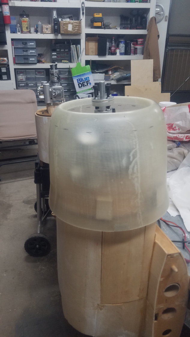
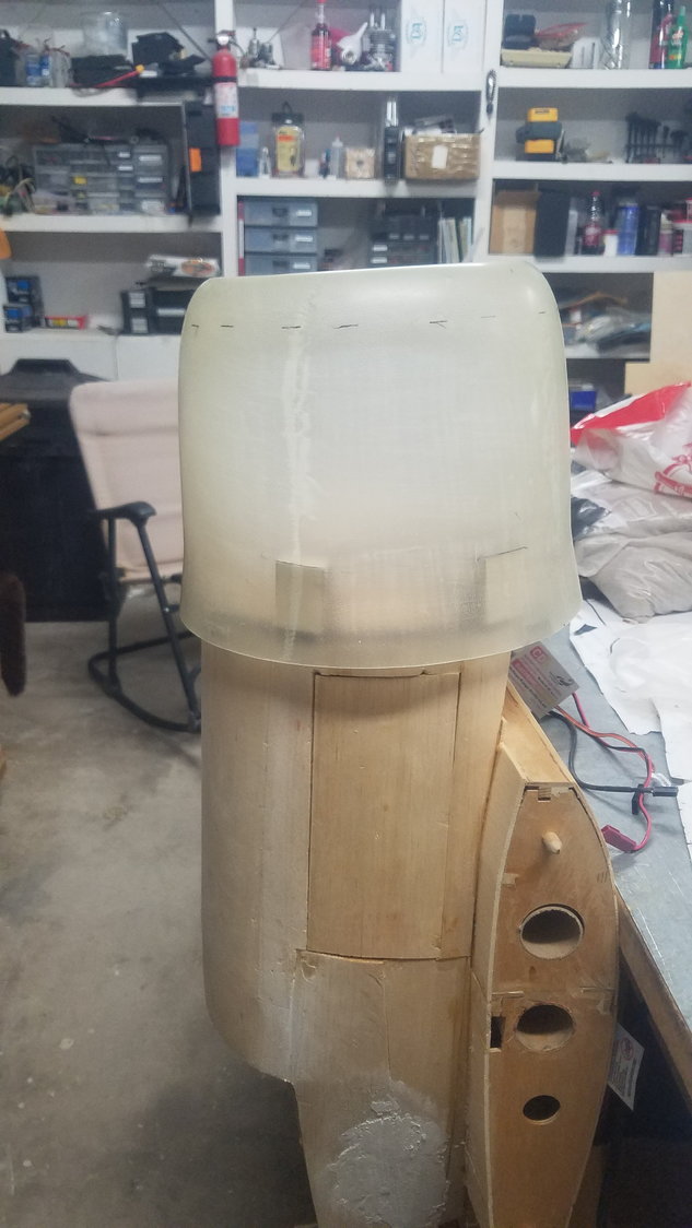
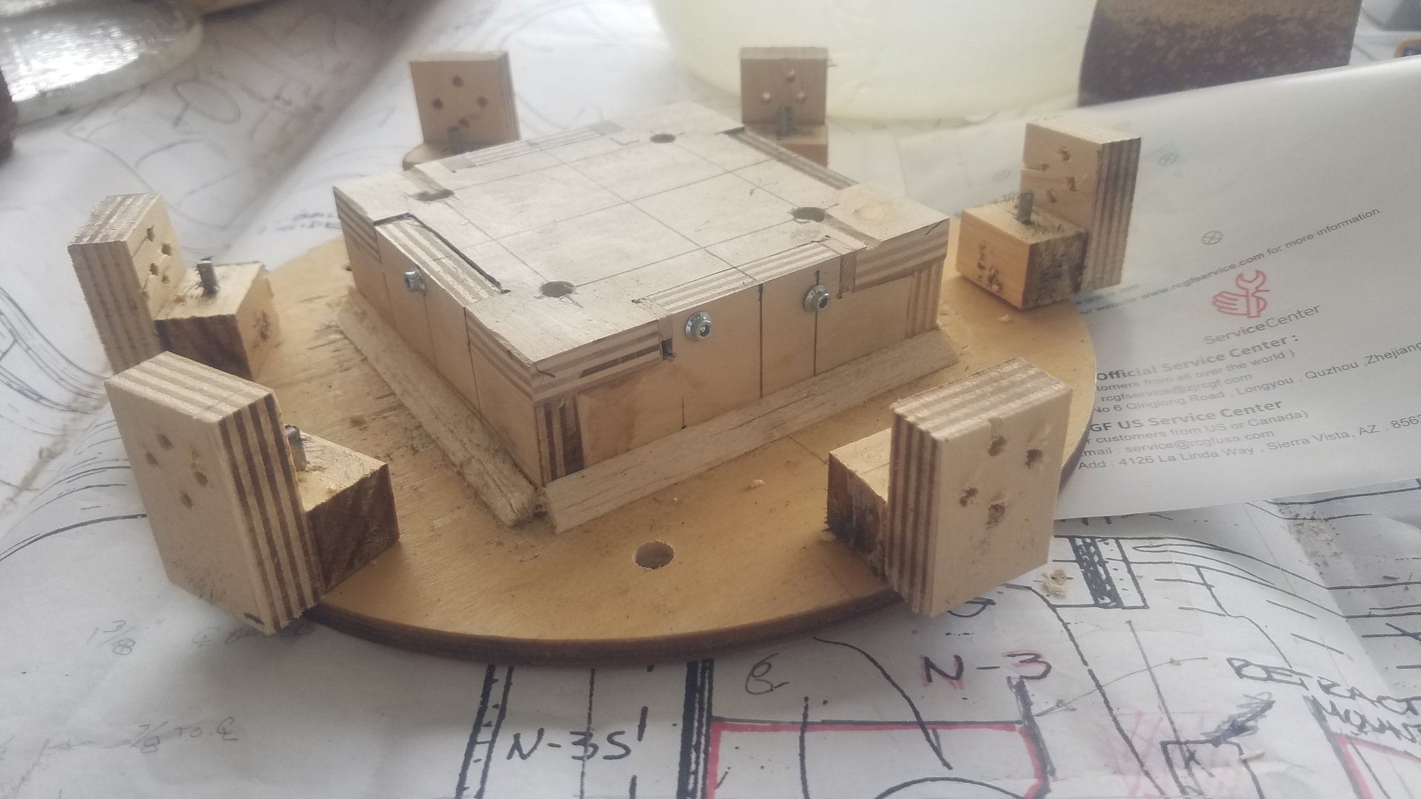
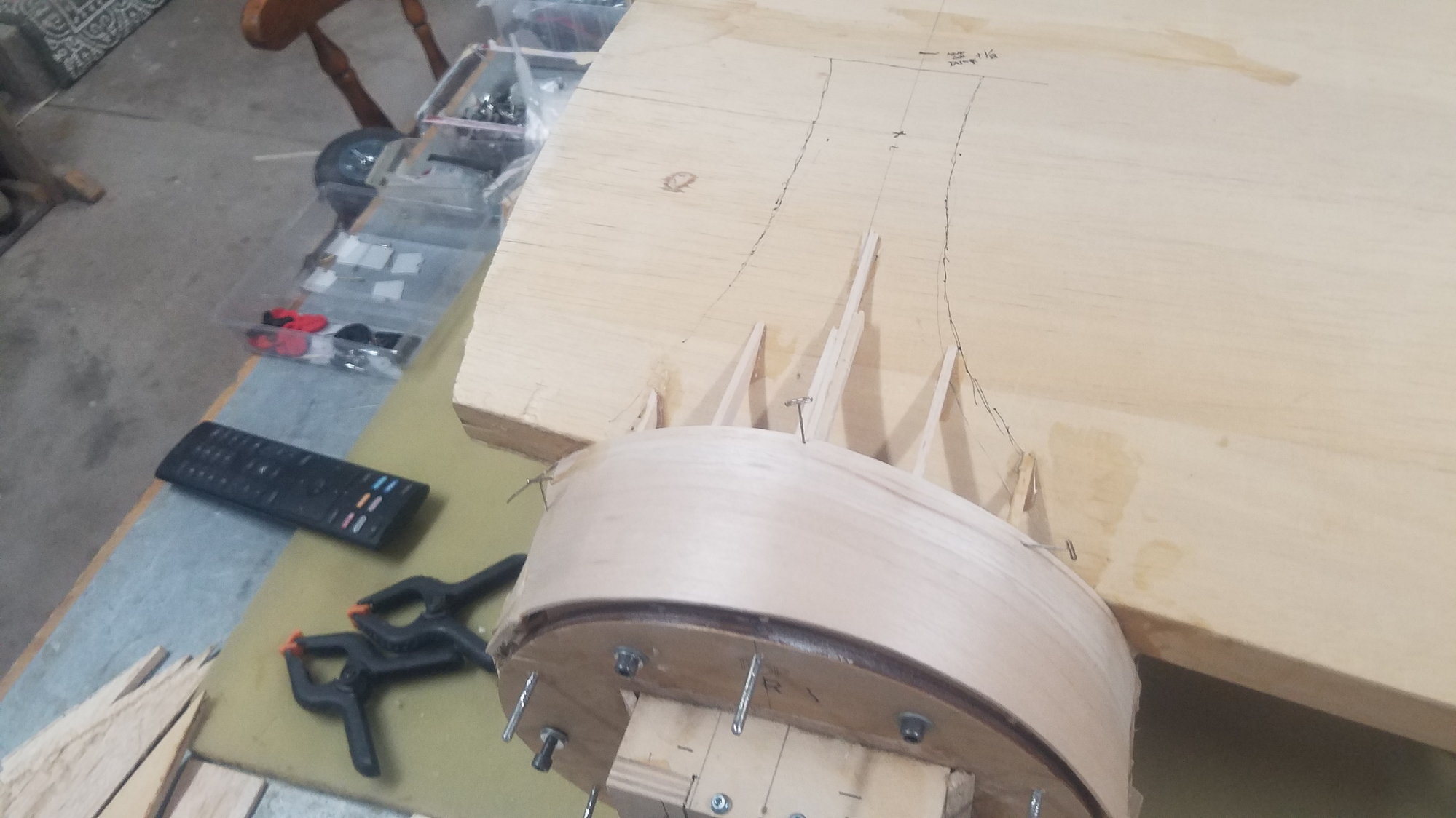
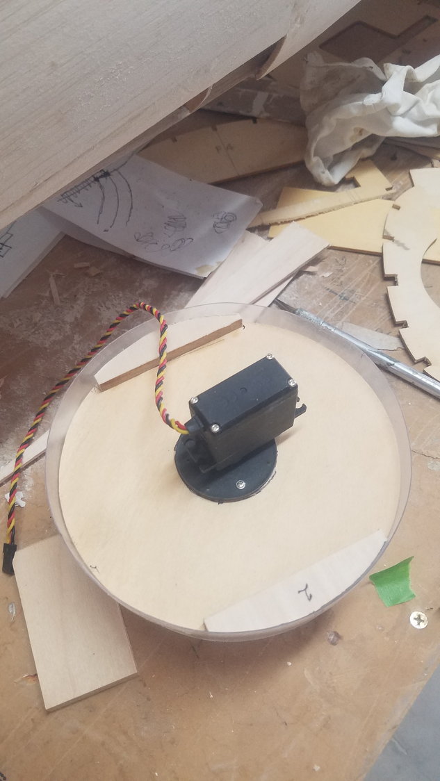
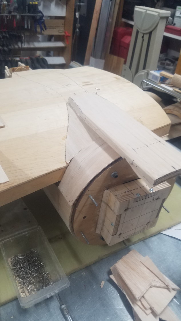
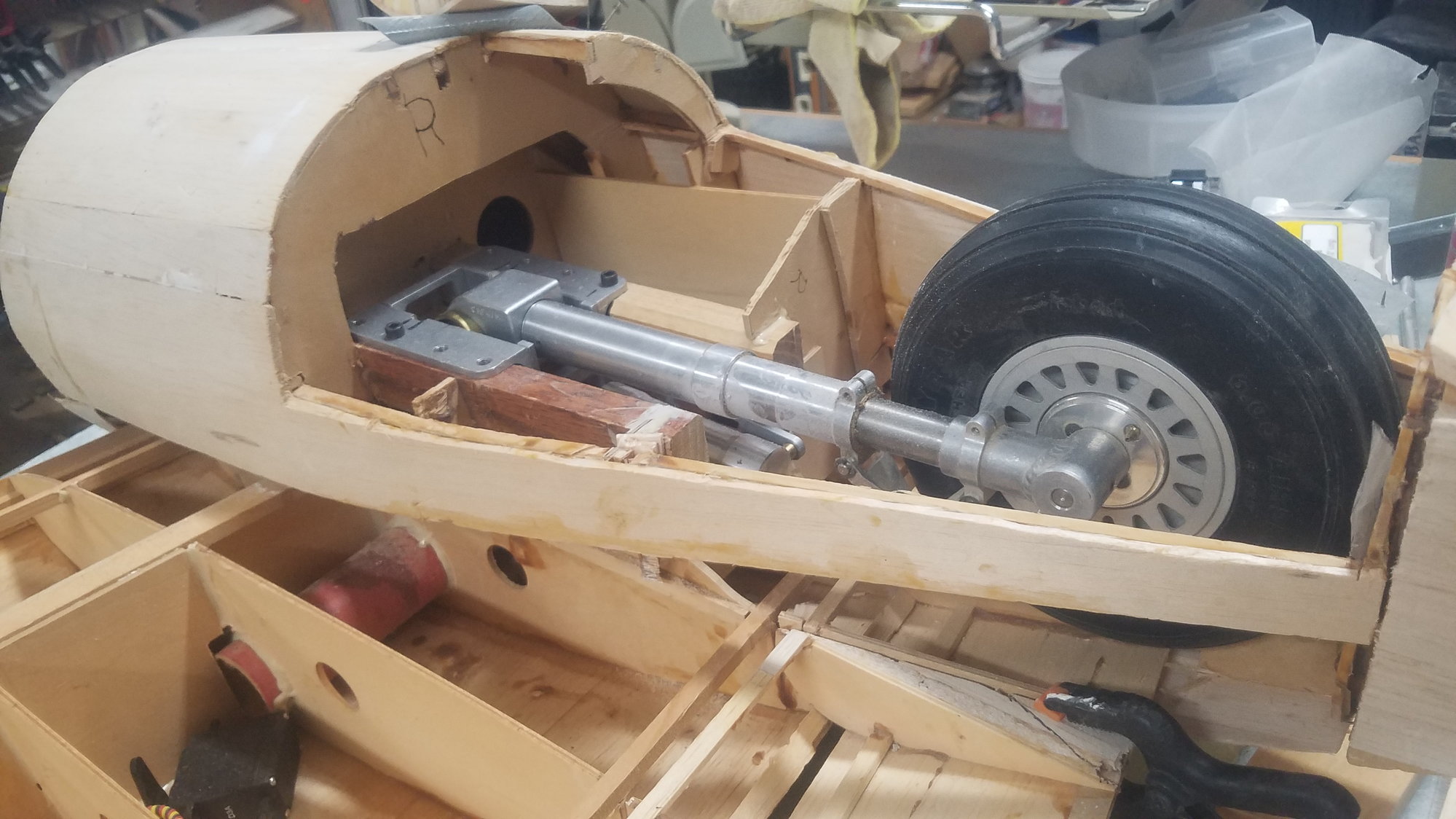
Continued work on turret. Getting correct diameter is a slow careful process. Servo mounted and will allow turret to be removed.
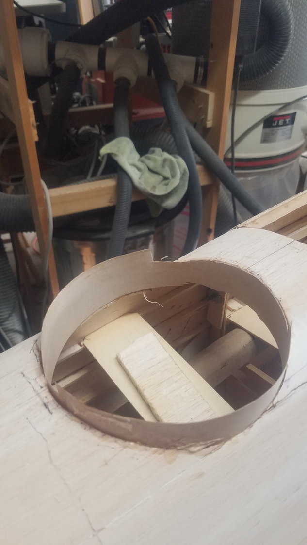
Getting banding installed so that turret will be able to rotate. Again, a slow process. Shows floor where servo will be mounted.
Attach pads installed so dome can be removed to work on internal components (guns, site) Will use very small screws to hold dome on base.
Installed one more section on tail.
Installed nacelle skin, another layer will go on top
Last edited by rossmick; 07-03-2022 at 08:48 PM. Reason: Added more photos
 07-05-2022, 04:20 PM
#90
Senior Member
Thread Starter
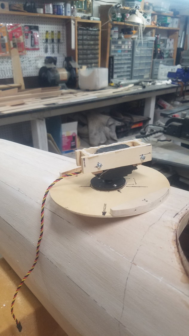
Built a box around servo mount so the turret can be removed by lifting it out by removing two screws.

Turret box glued in place showing the two screws that hold the servo and turret in place. These can be removed, and the turret lifted out.
Slowly getting the turret installed
Looking pretty good.
07-05-2022, 05:18 PM
#91
Senior Member
Thread Starter
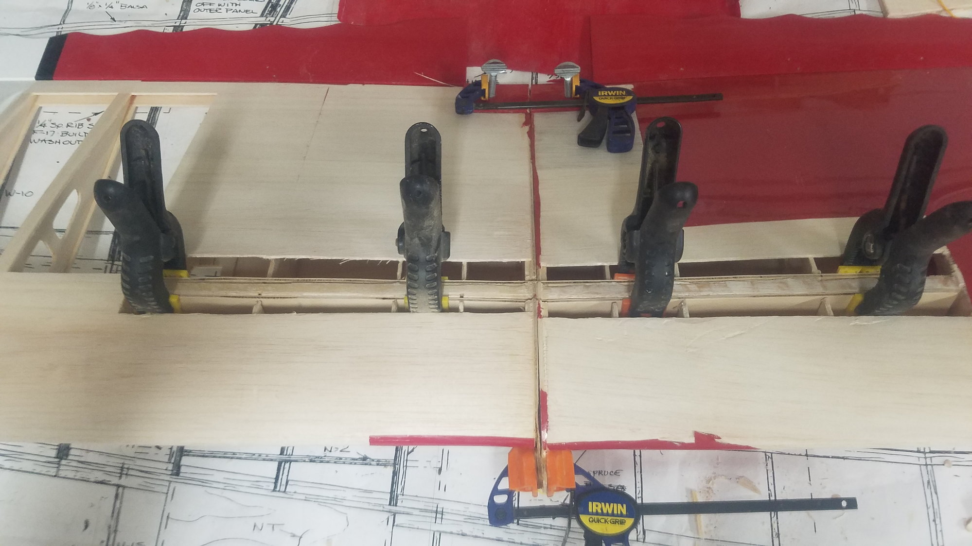
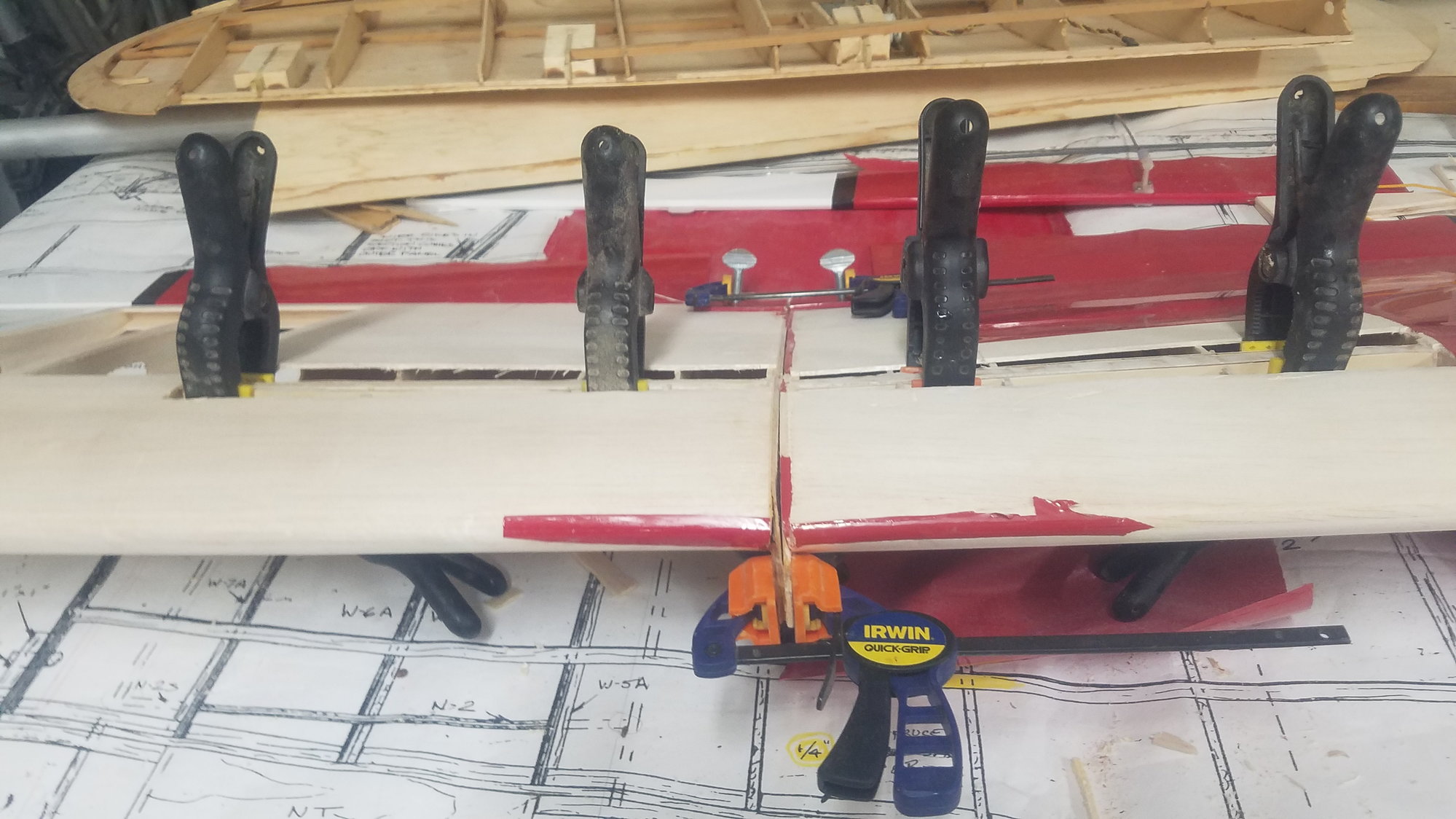
Actually, spent some of yesterday and today repairing a friend's Stik wing. He had two damaged wings, Luckly, had opposite sides damaged in separate crashes.
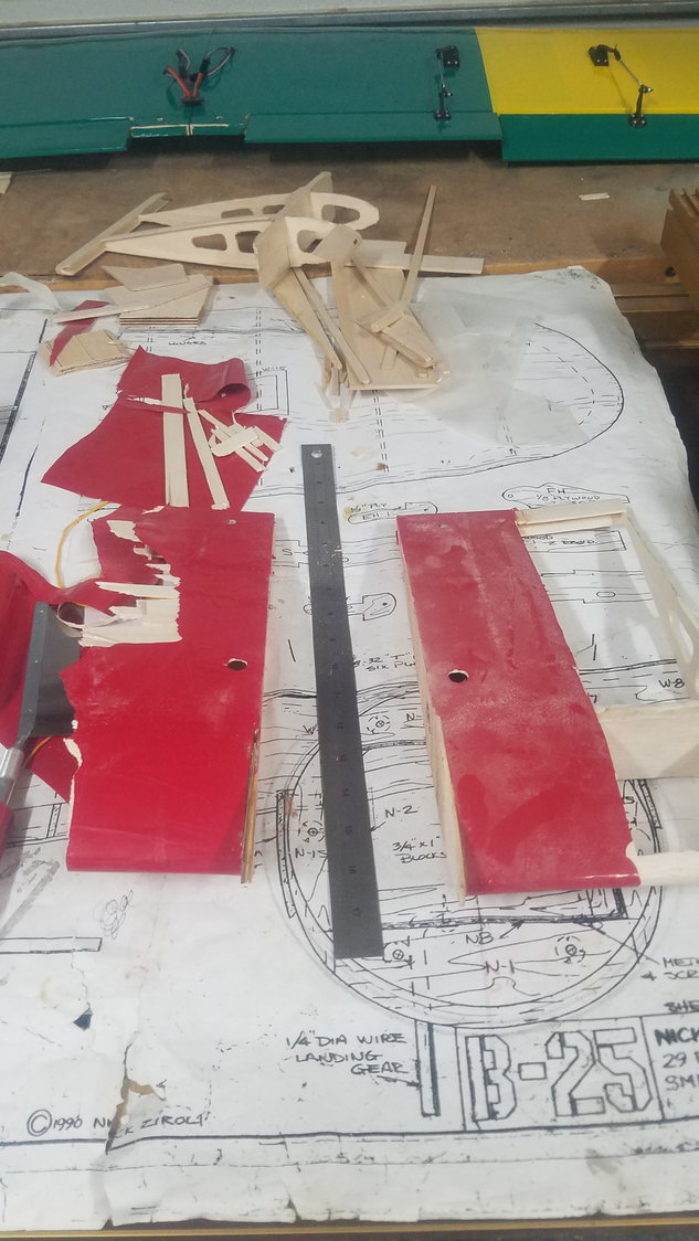
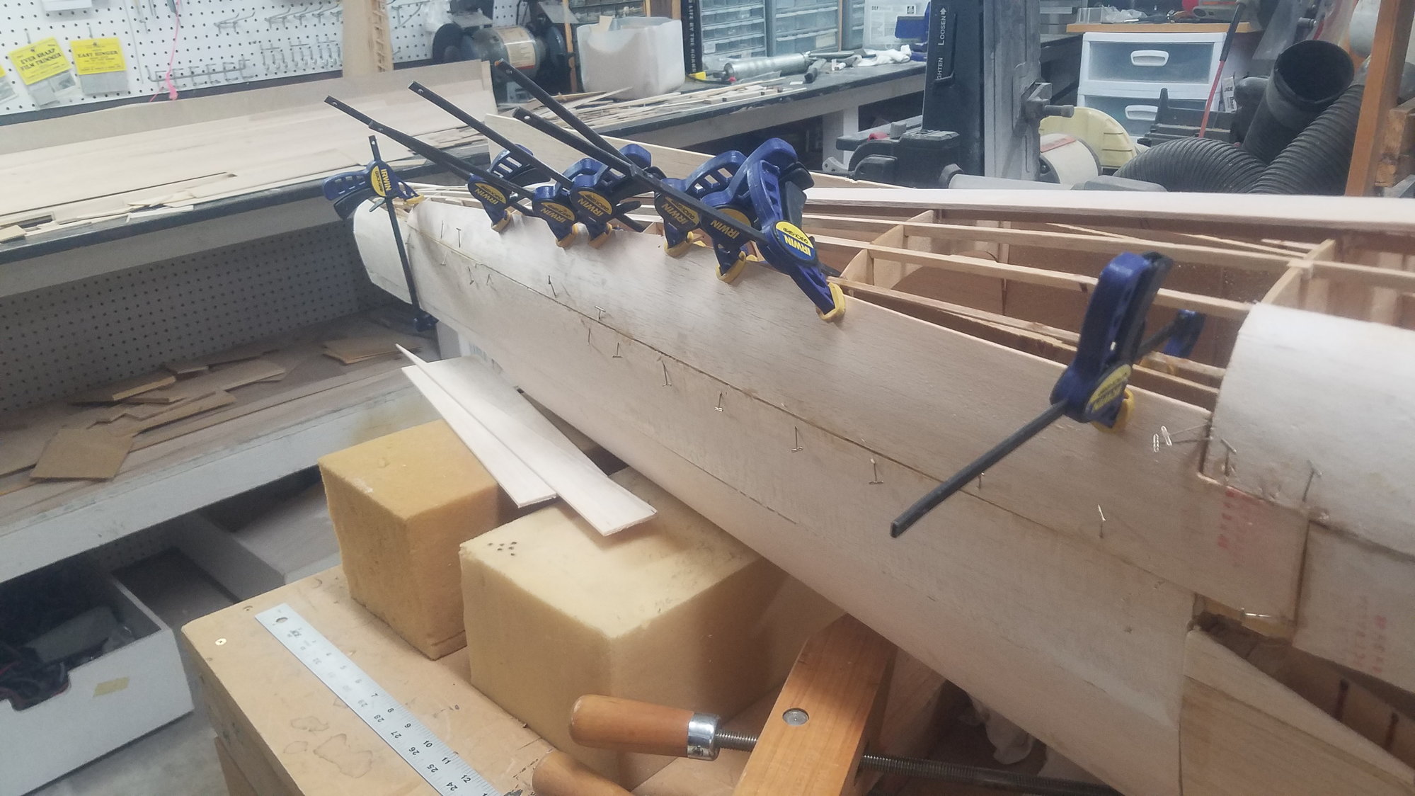
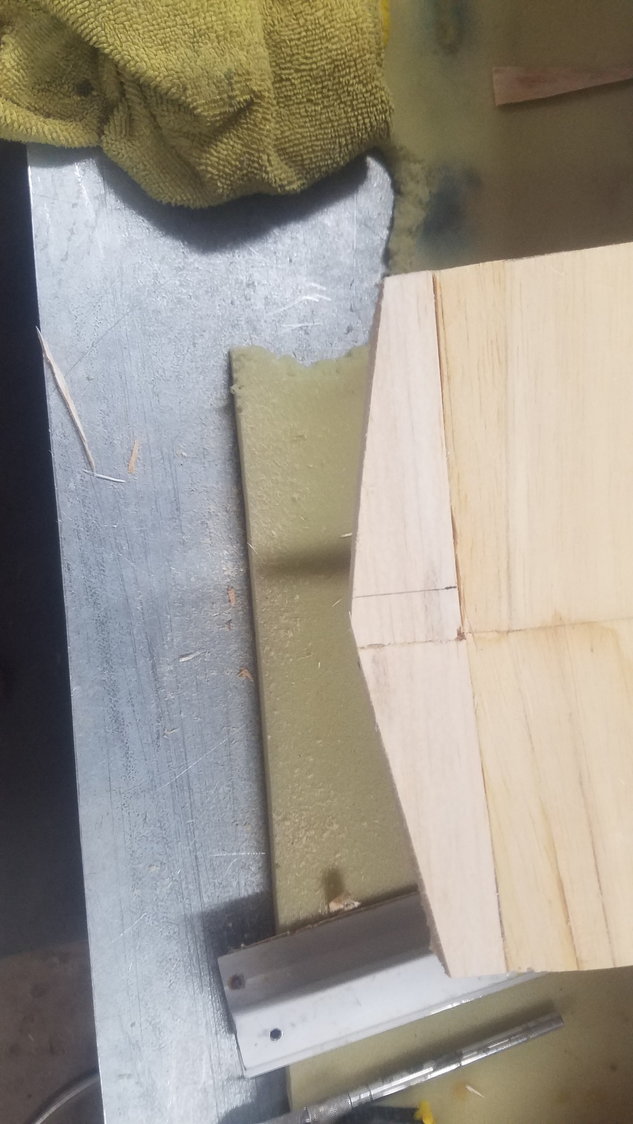
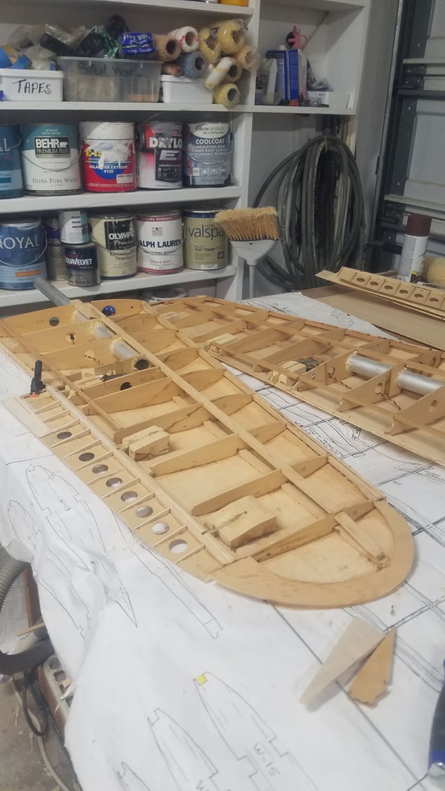
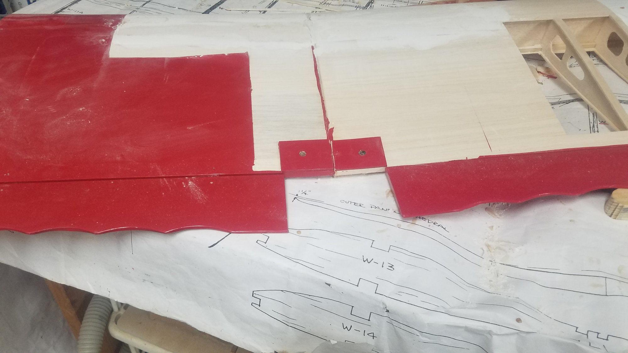
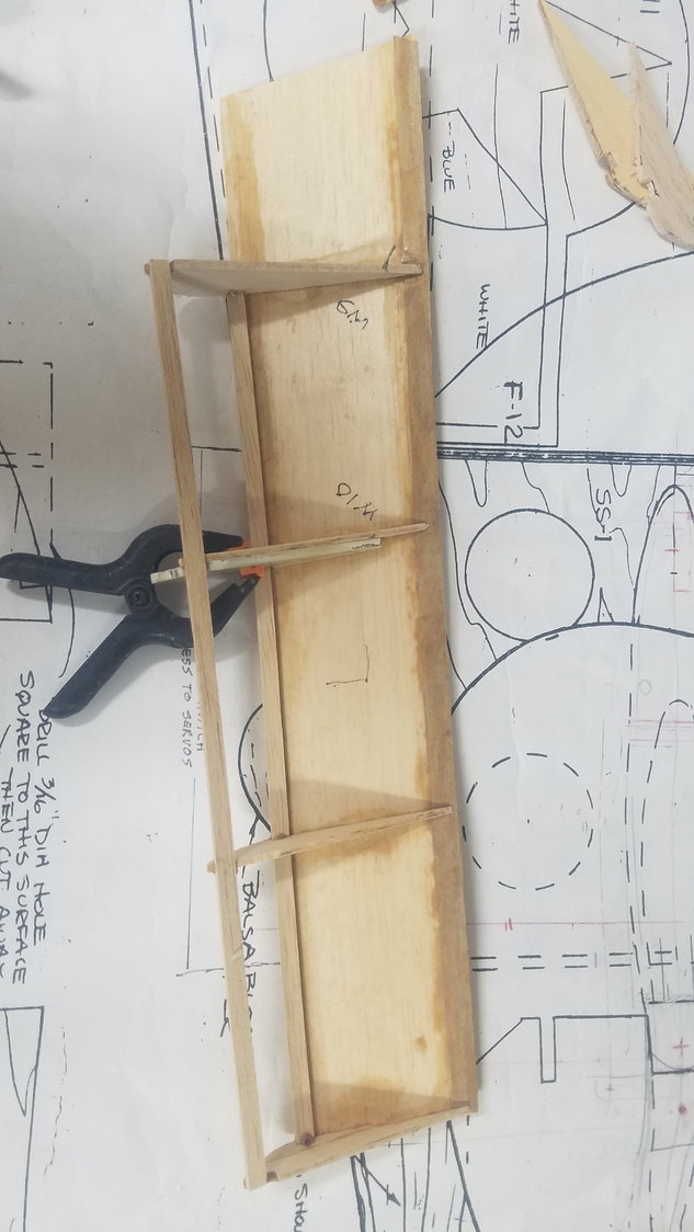
Cut on the center joining line of the two damaged wing sections using the band saw. Lucky, he had two undamaged opposite sections.
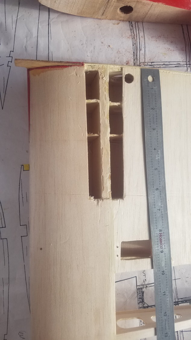
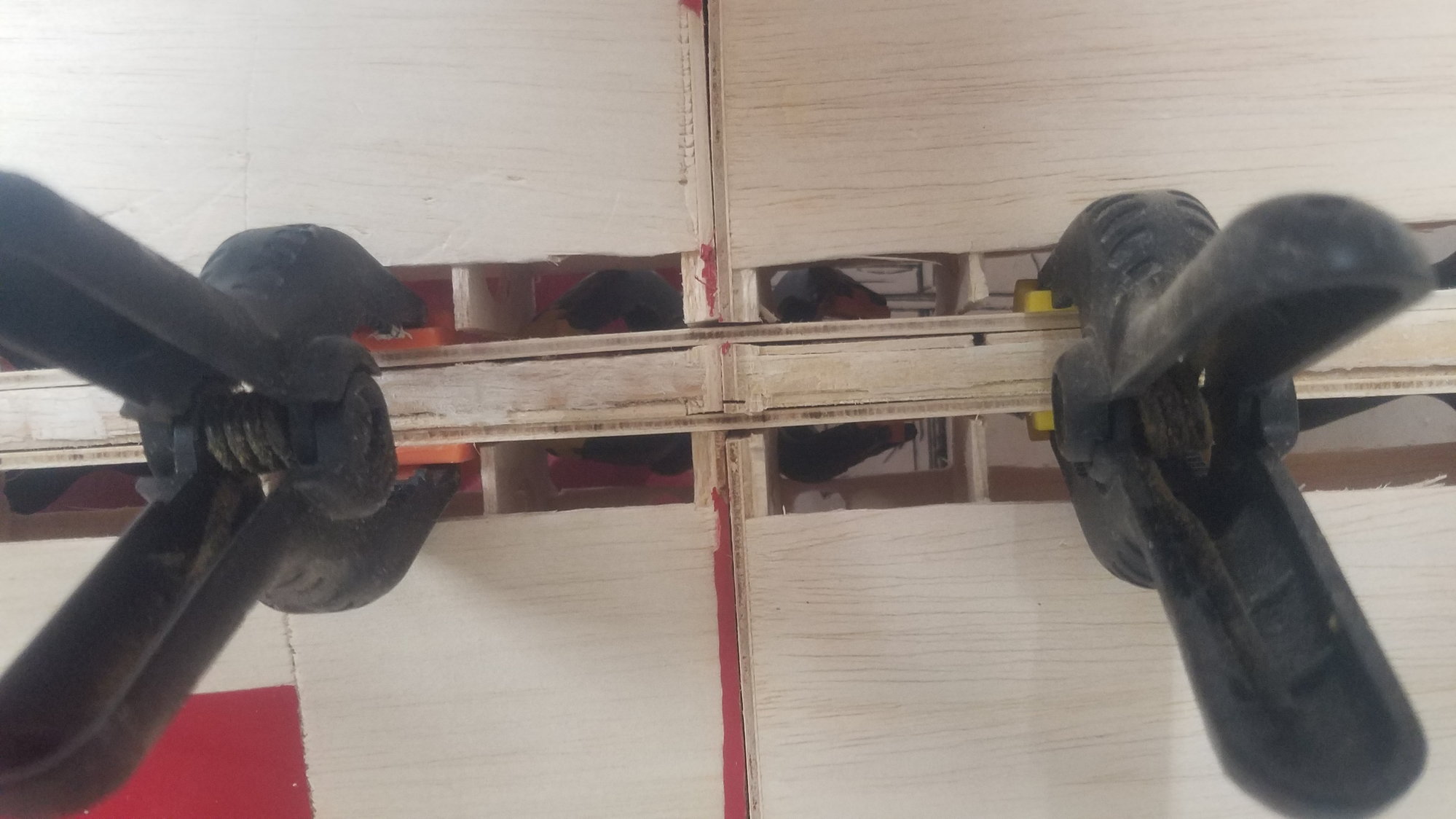
Removed skin around spar to allow for new spars to be clamped in place. Actually, increased depth to the fourth rib after photo.

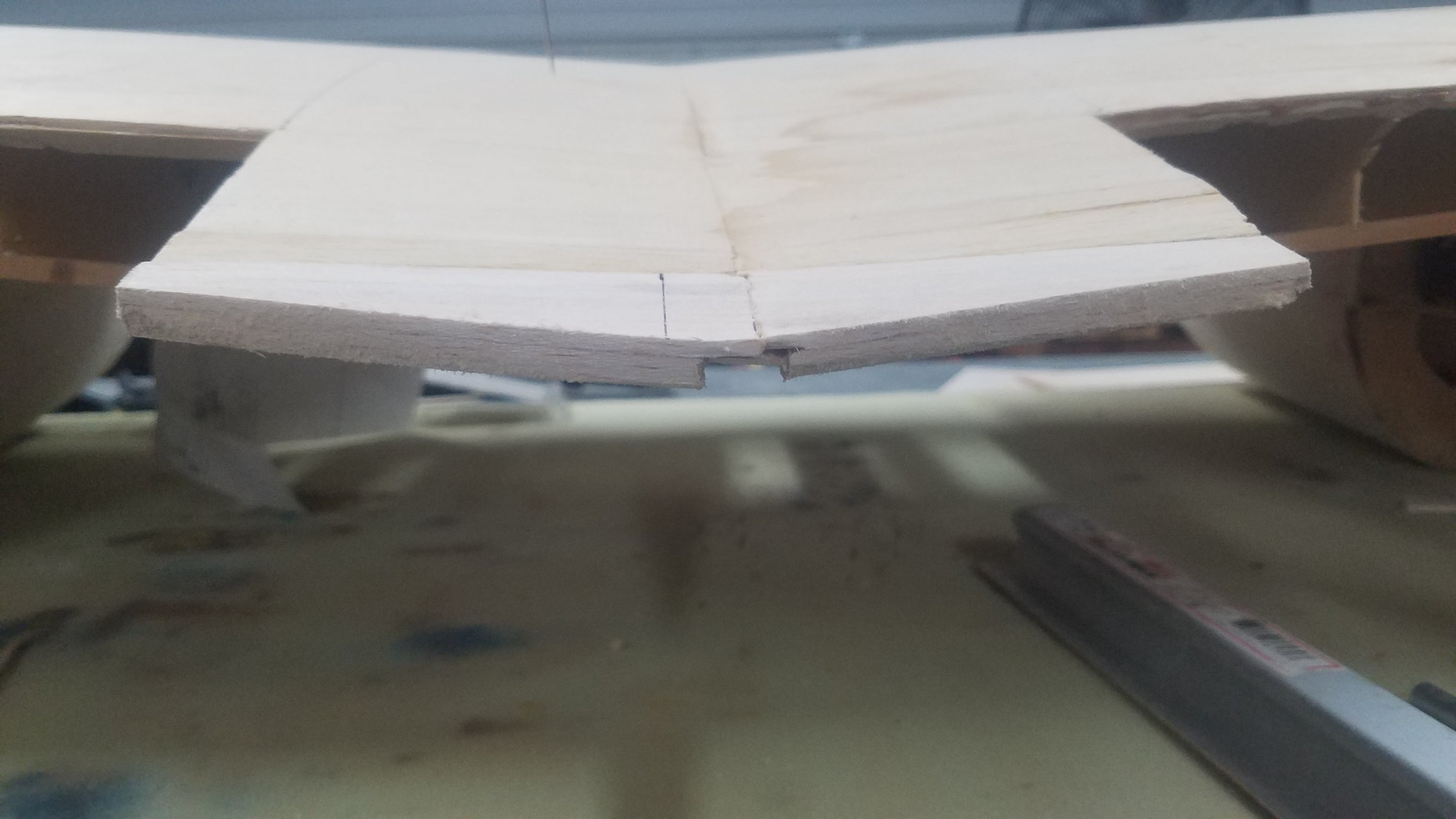
End view of start of cuts for new spars, one on each side of existing main spar.
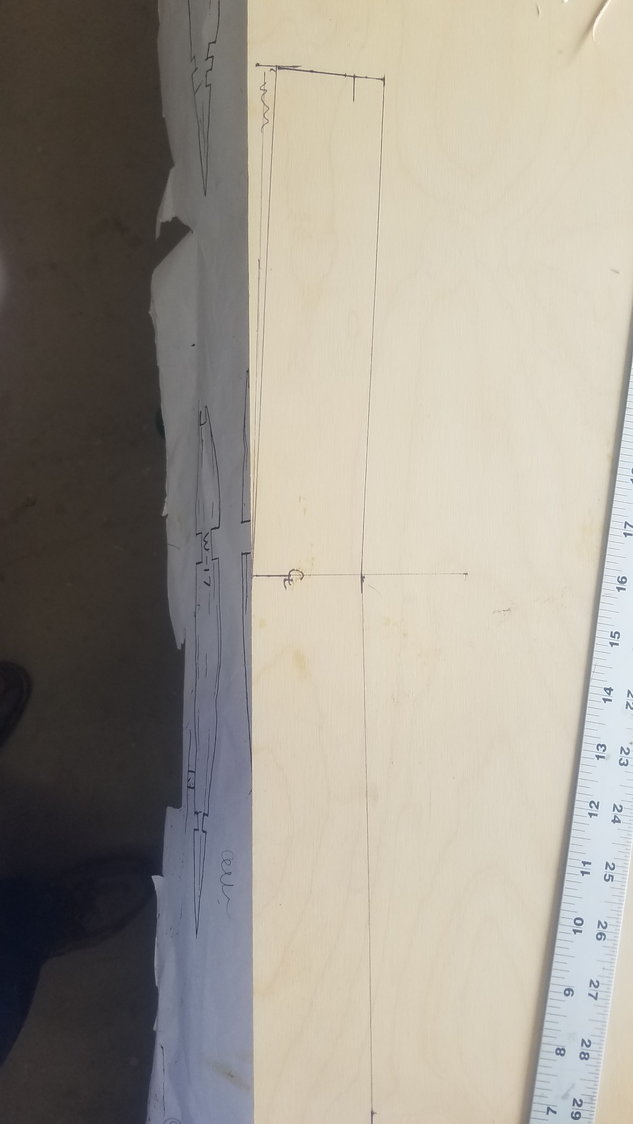
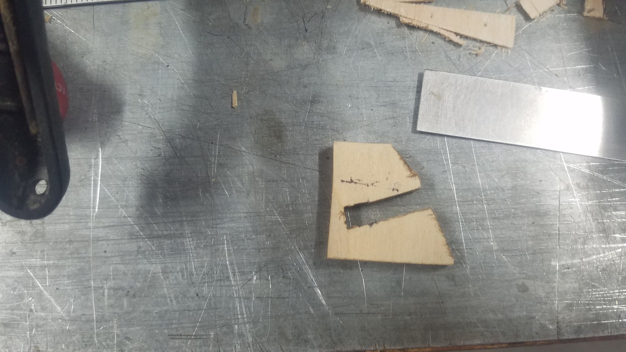
Layout of spar on 1/8" ply.
Two spars cut out with proper dihedral.
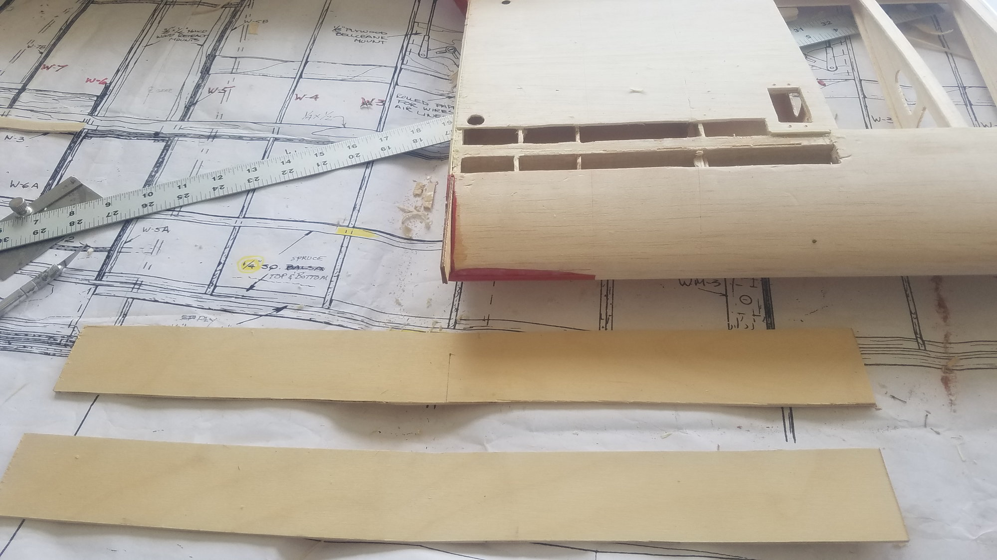
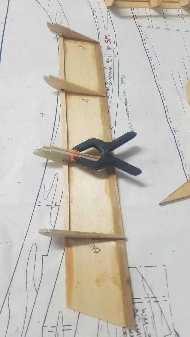
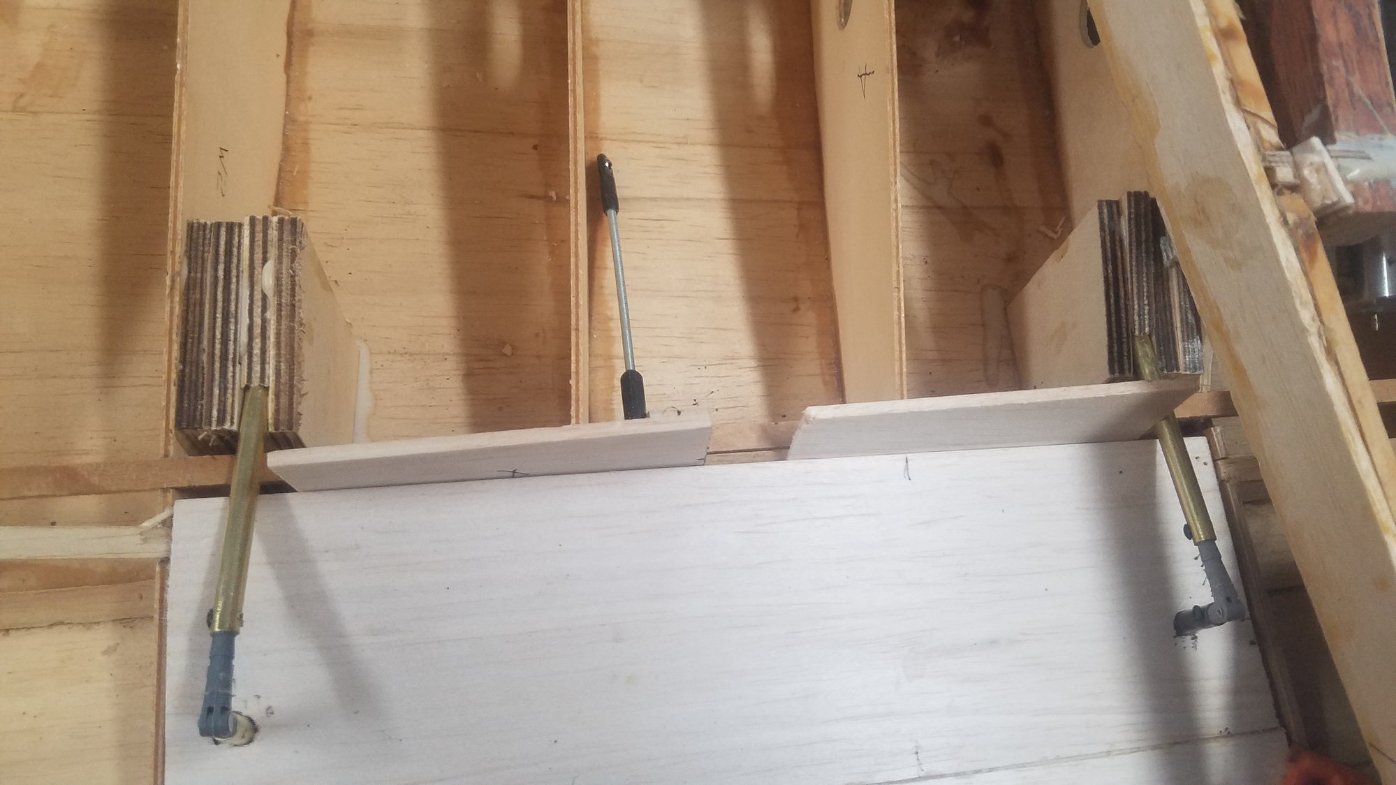
Shows new spars in place on each side of main spar. Ribs cut back to accept the spars.
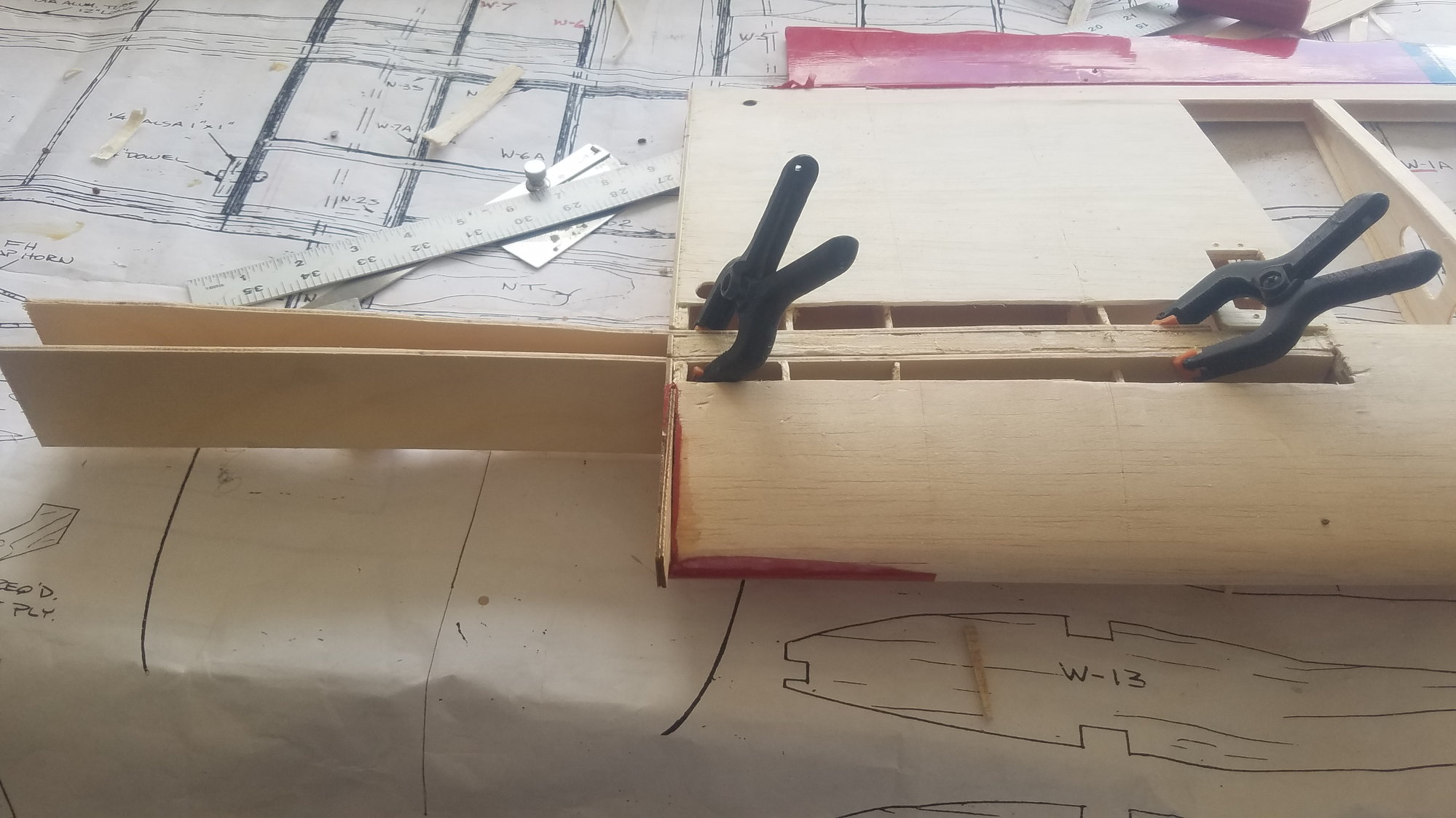
Dry fit new spars clear to fourth rib.
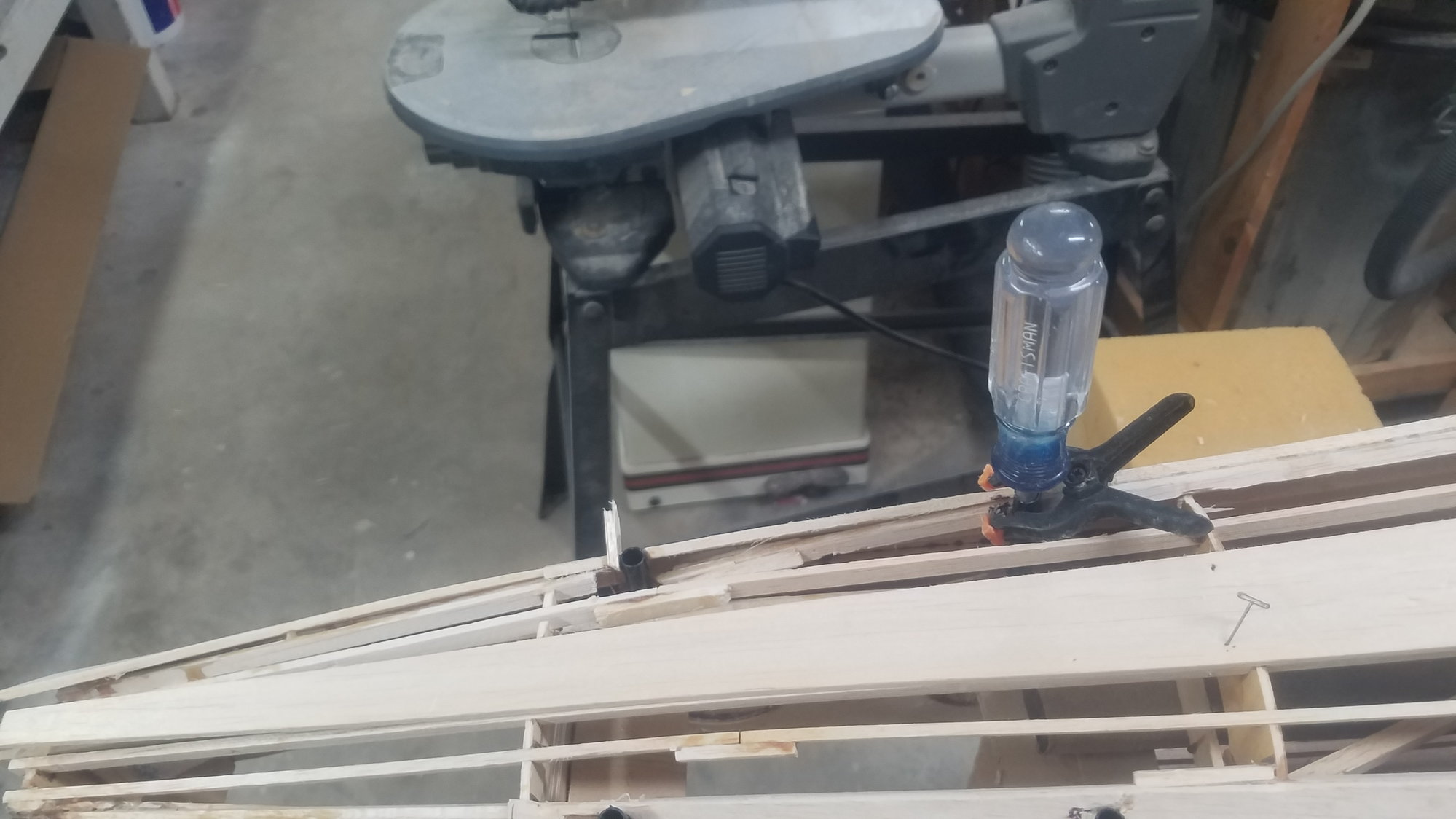
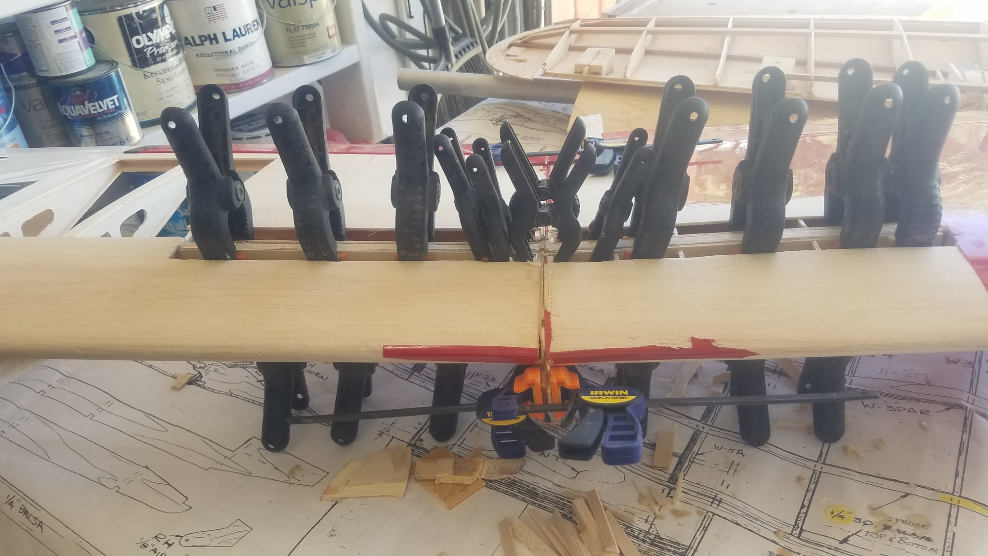
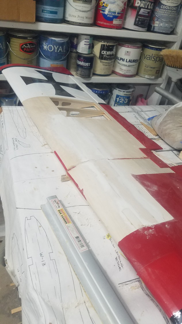
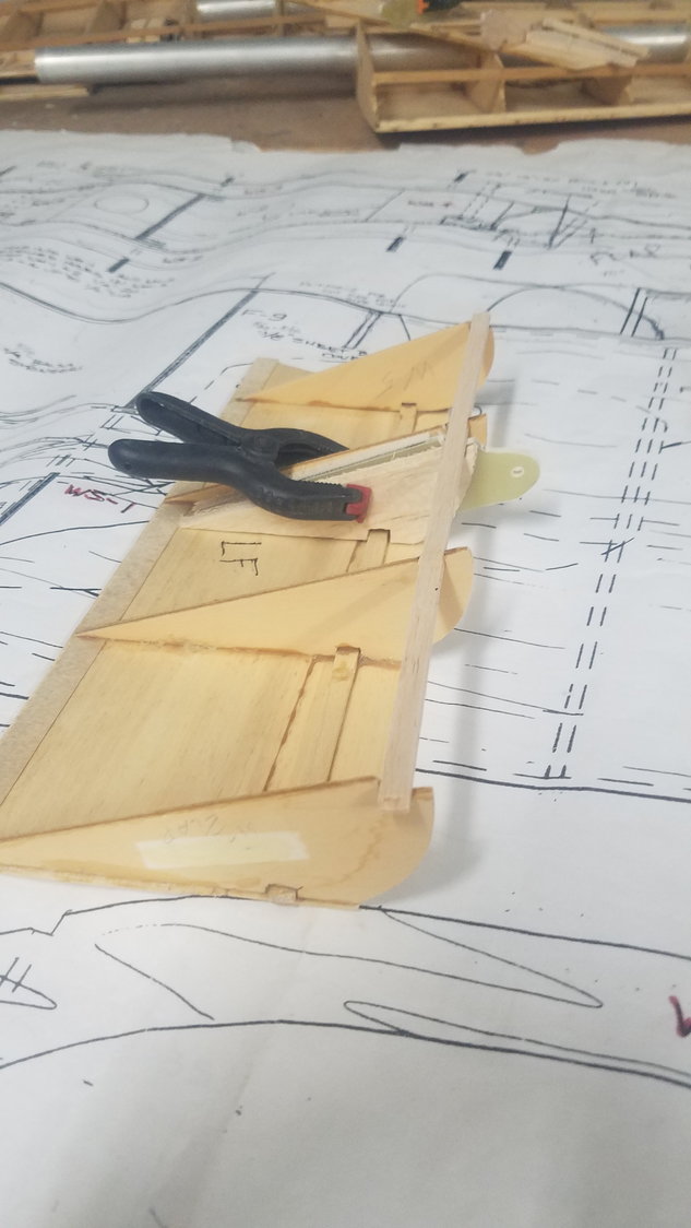
New spars clamped in place covering the top and bottom spruce members.
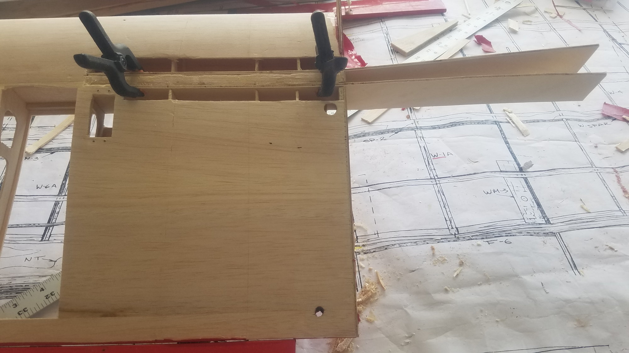
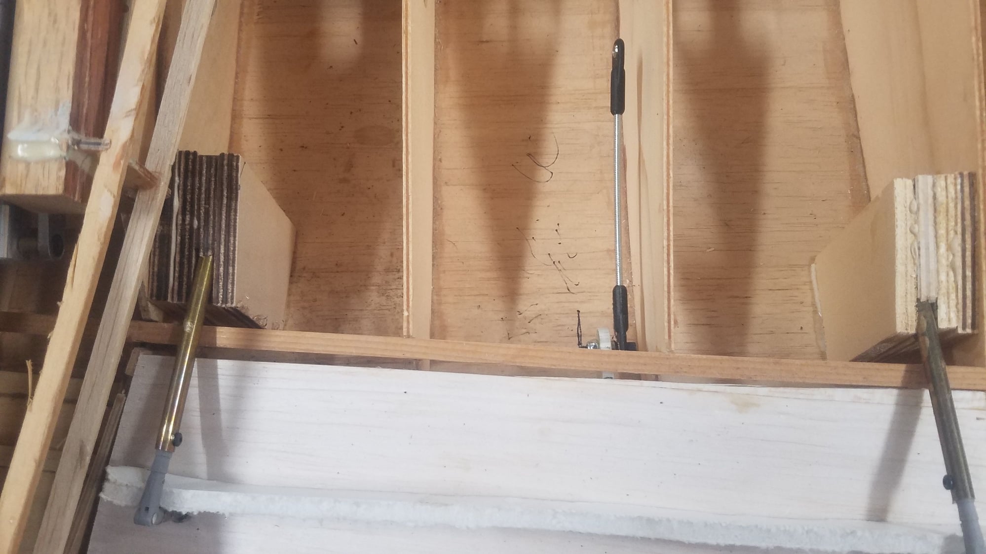
Another view of new spars.
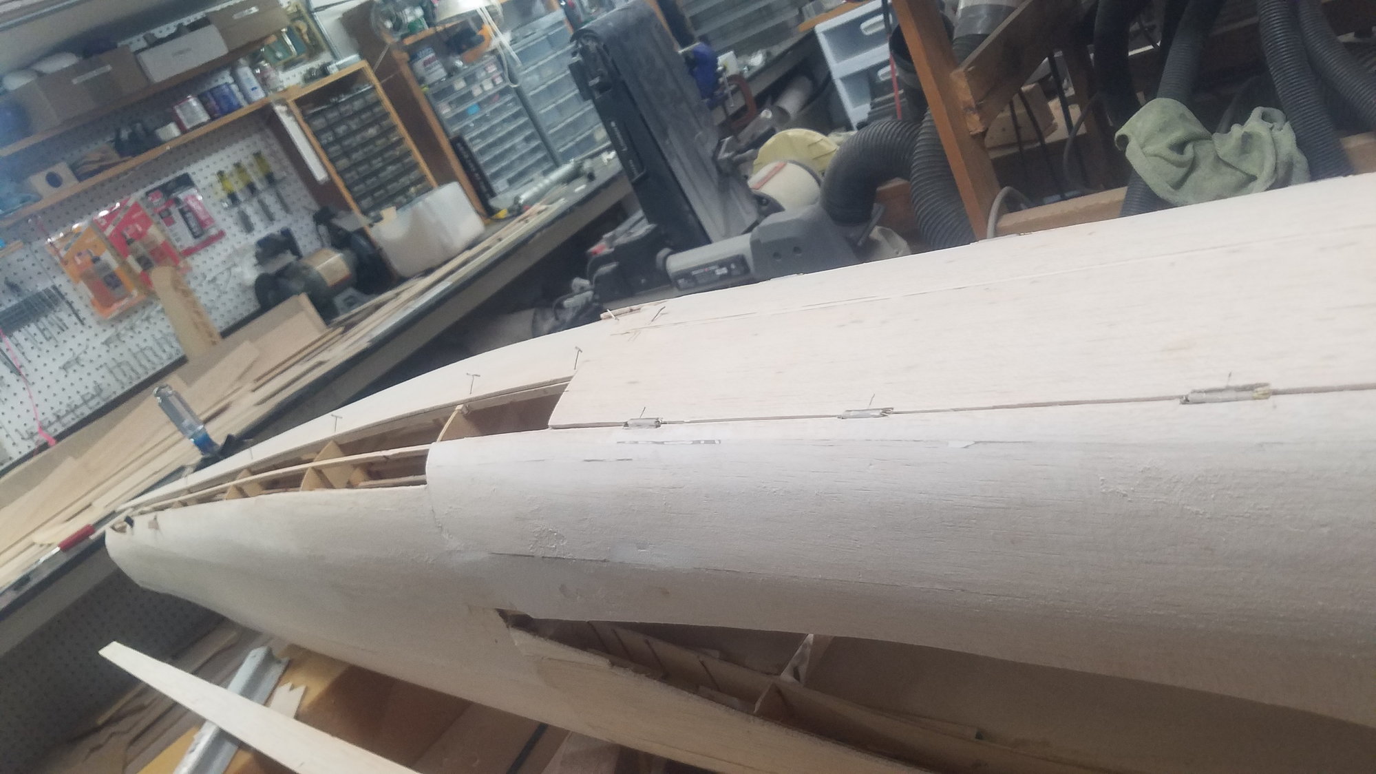
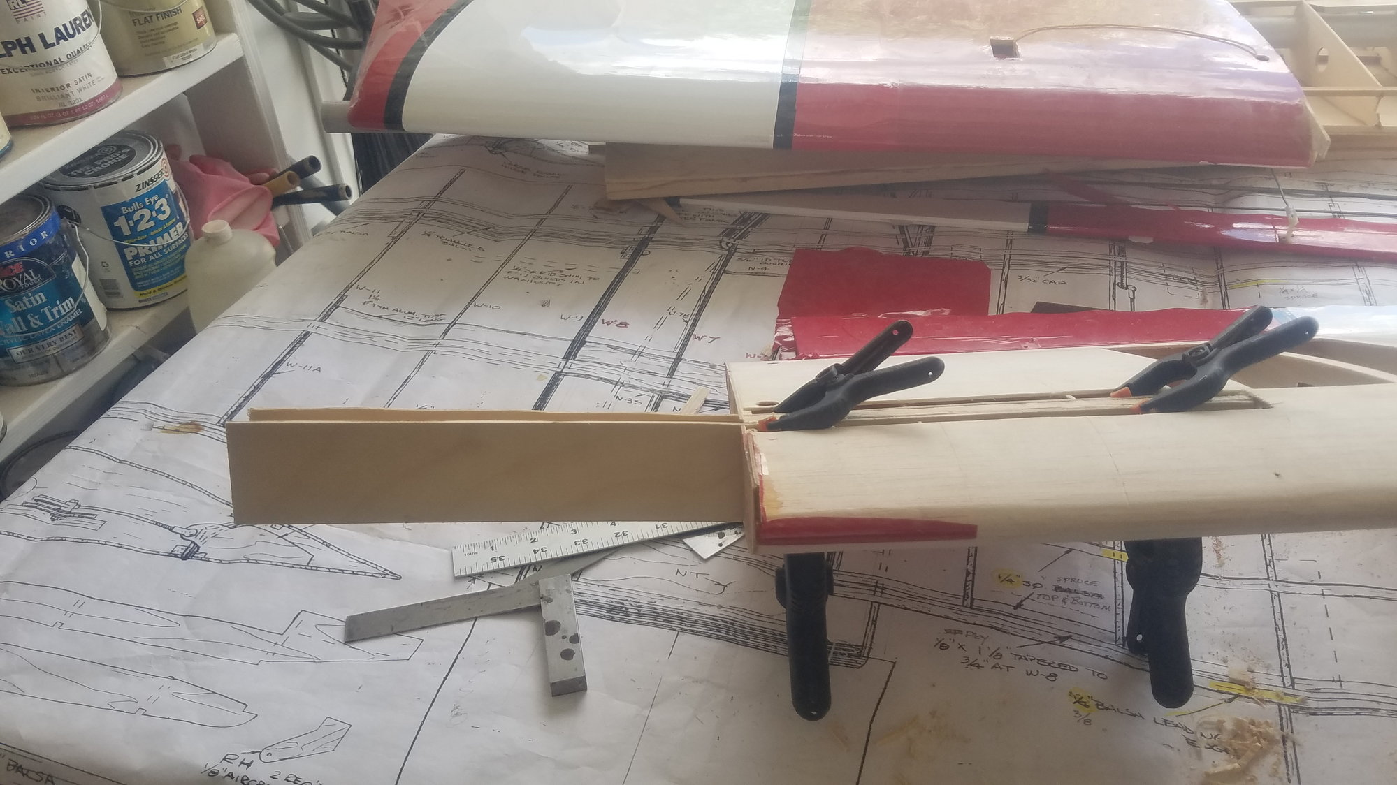
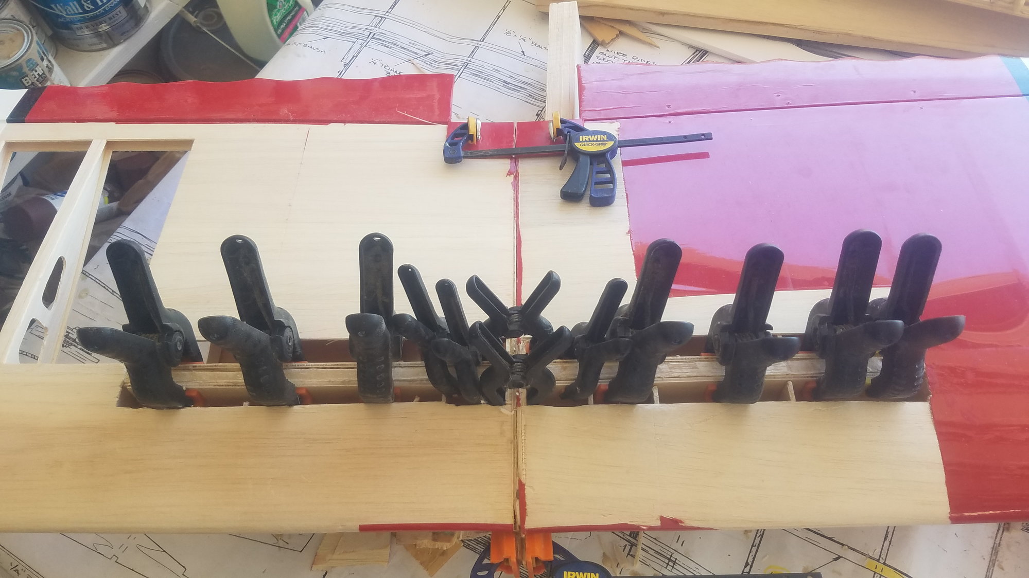
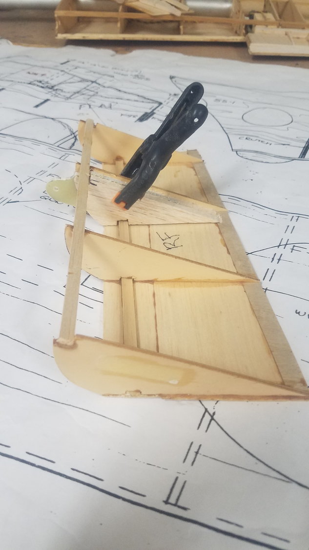
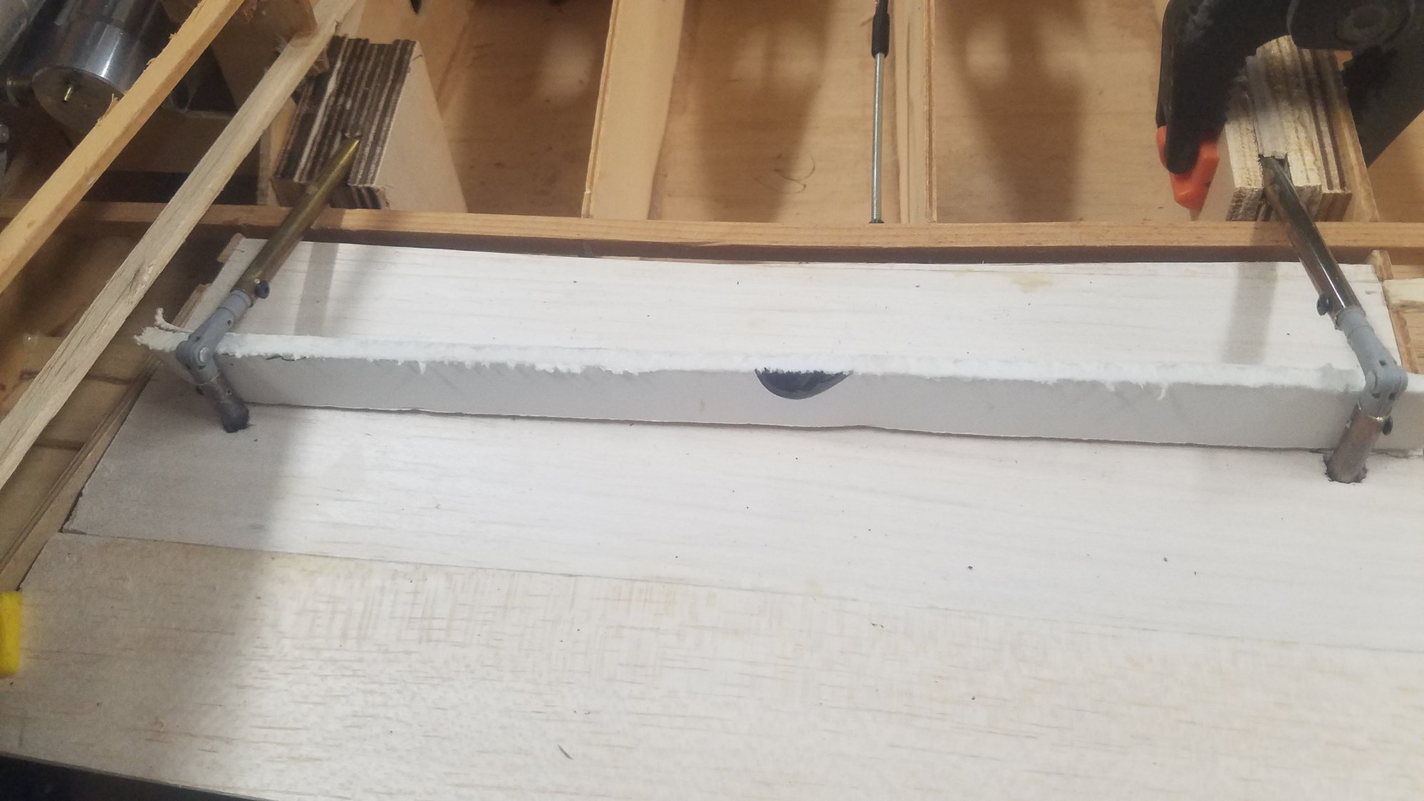
Both wing sections dry fit attached with new spars.
Another view of joined condition.
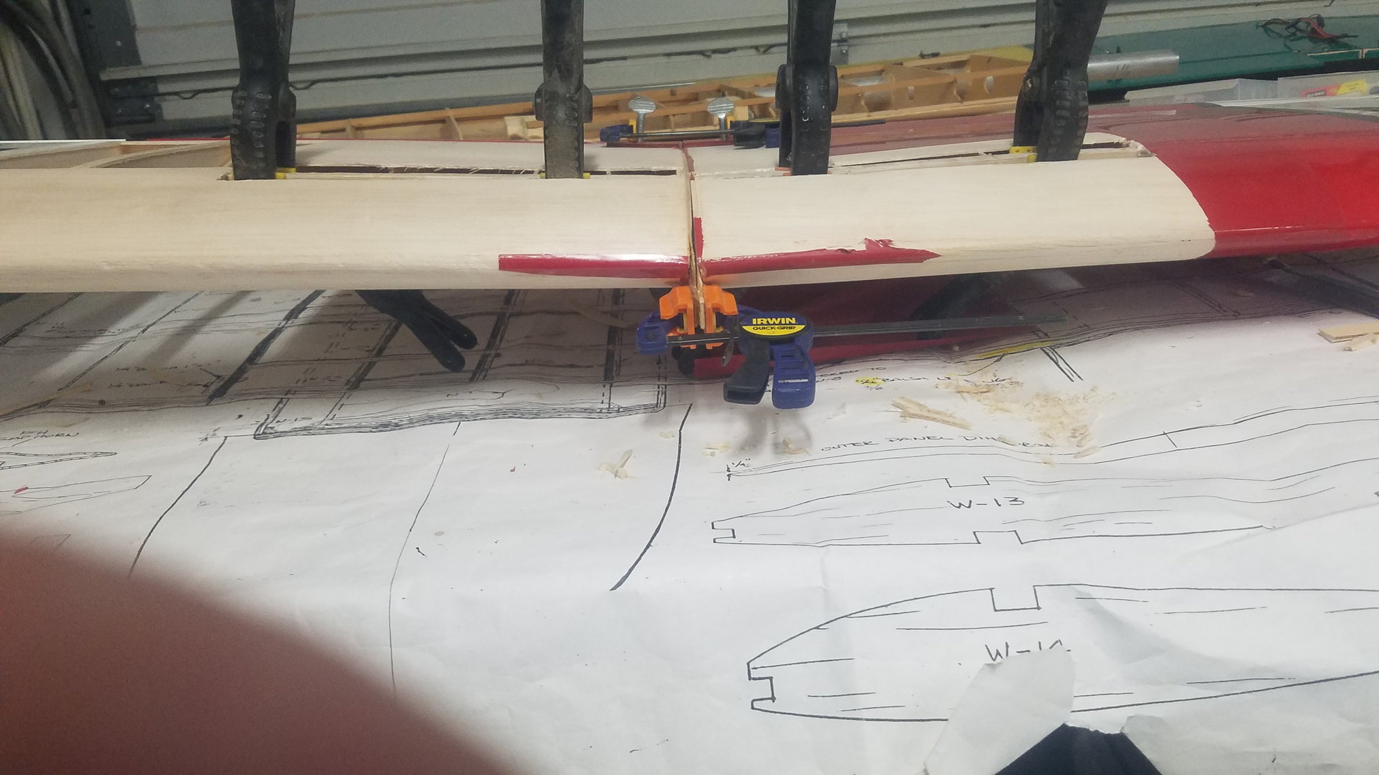
Shows dihedral of the wing.
Cut on the center joining line of the two damaged wing sections using the band saw. Lucky, he had two undamaged opposite sections.
Removed skin around spar to allow for new spars to be clamped in place. Actually, increased depth to the fourth rib after photo.
End view of start of cuts for new spars, one on each side of existing main spar.
Layout of spar on 1/8" ply.
Two spars cut out with proper dihedral.
Shows new spars in place on each side of main spar. Ribs cut back to accept the spars.
Dry fit new spars clear to fourth rib.
New spars clamped in place covering the top and bottom spruce members.
Another view of new spars.
Both wing sections dry fit attached with new spars.
Another view of joined condition.
Shows dihedral of the wing.
Last edited by rossmick; 07-05-2022 at 05:25 PM. Reason: Text
07-06-2022, 04:25 PM
#92
Senior Member
Thread Starter
Turret hold down concept changed as screws were hard to locate and impossible to screw back in due to their location. Now using push rod idea. Shows outer push rod with pin retracted allowing servo and turret to be removed.
Push rod with pin extended (closed position) which will hold servo in place.
Push rods in hatch area where they can be pulled out or pushed in. Will install wire inserts that will hold push rod in closed position.
ddddd
 07-09-2022, 07:17 PM
#94
Senior Member
Thread Starter
Did not take any photos over the last couple of days, so I am catching up today.
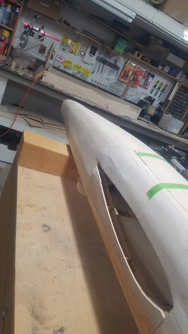
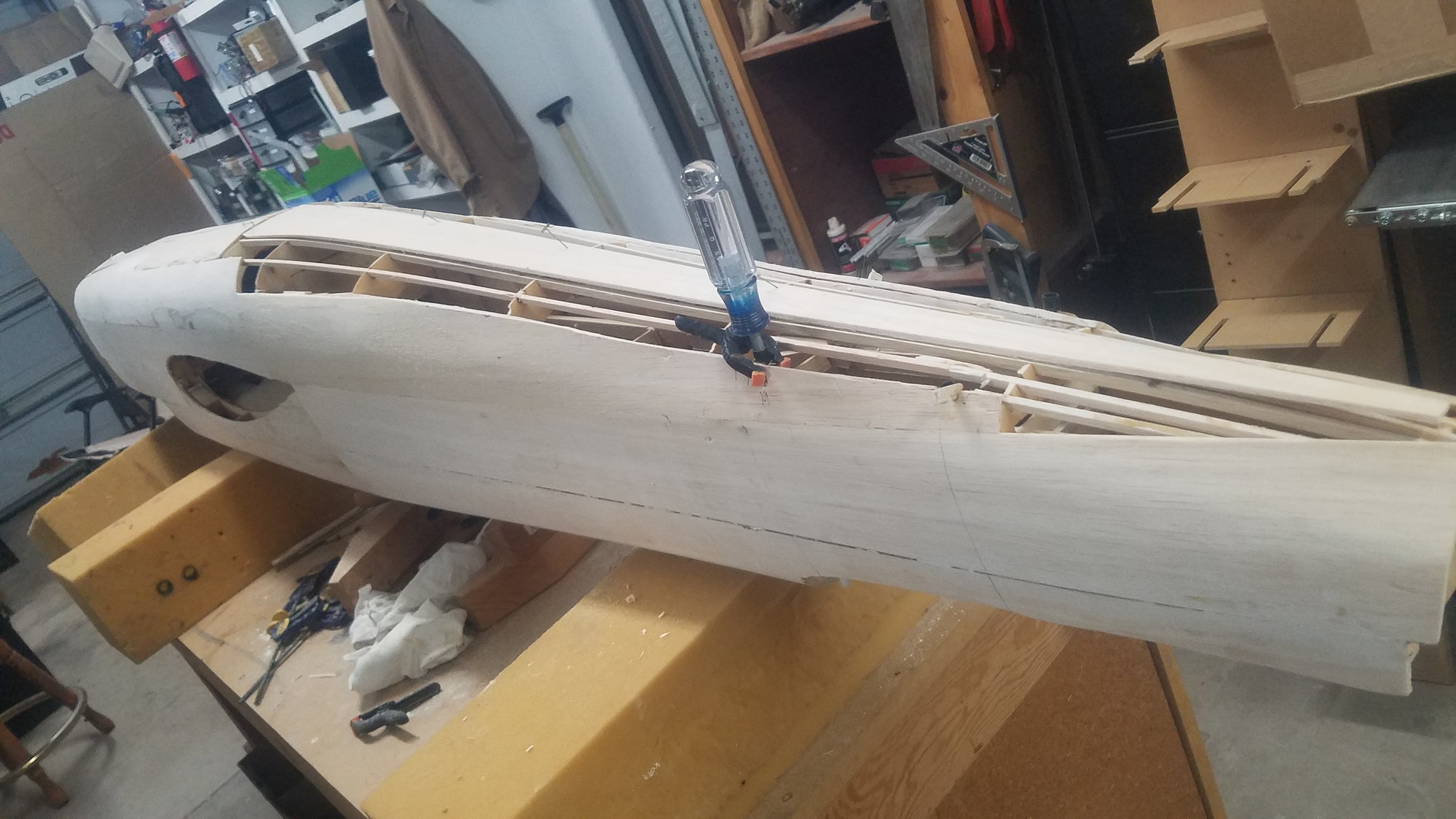
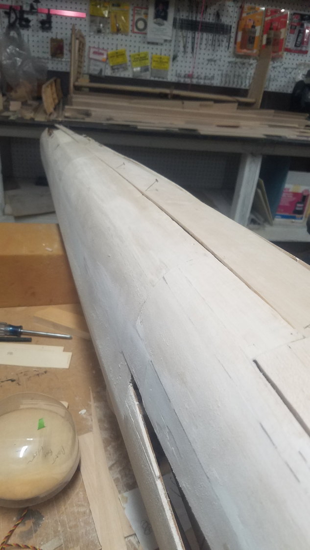
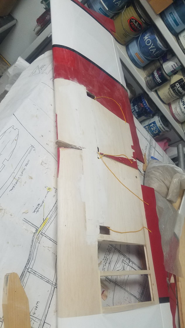
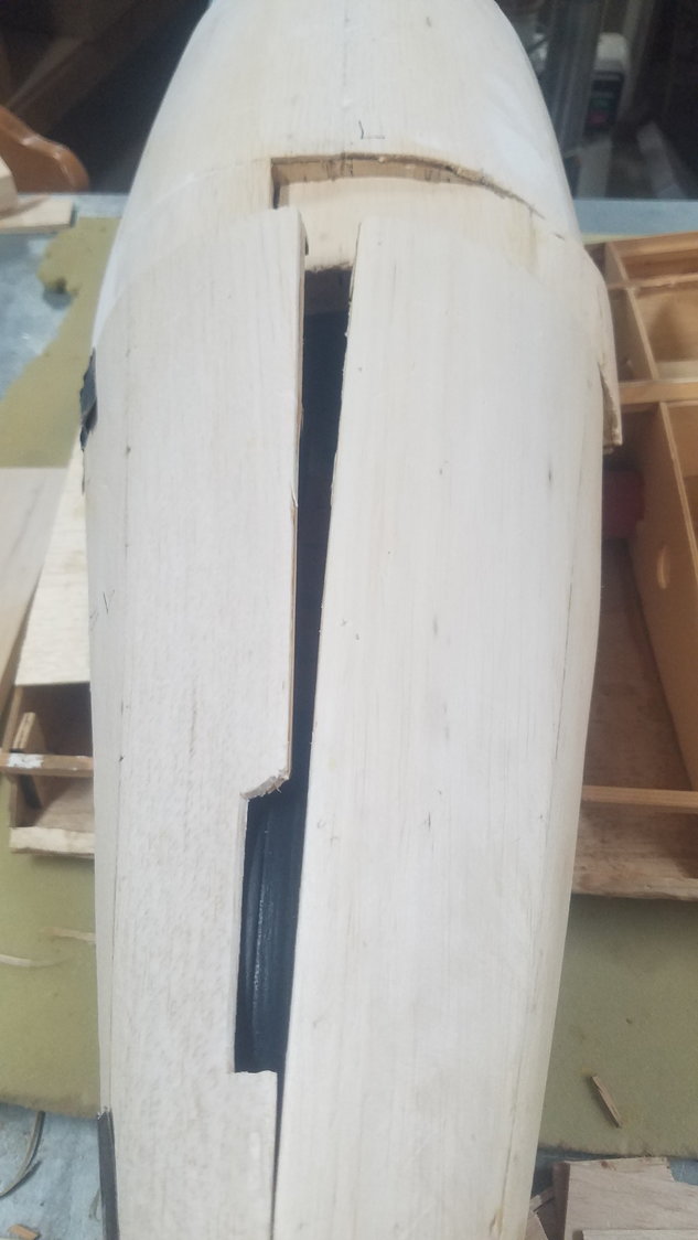
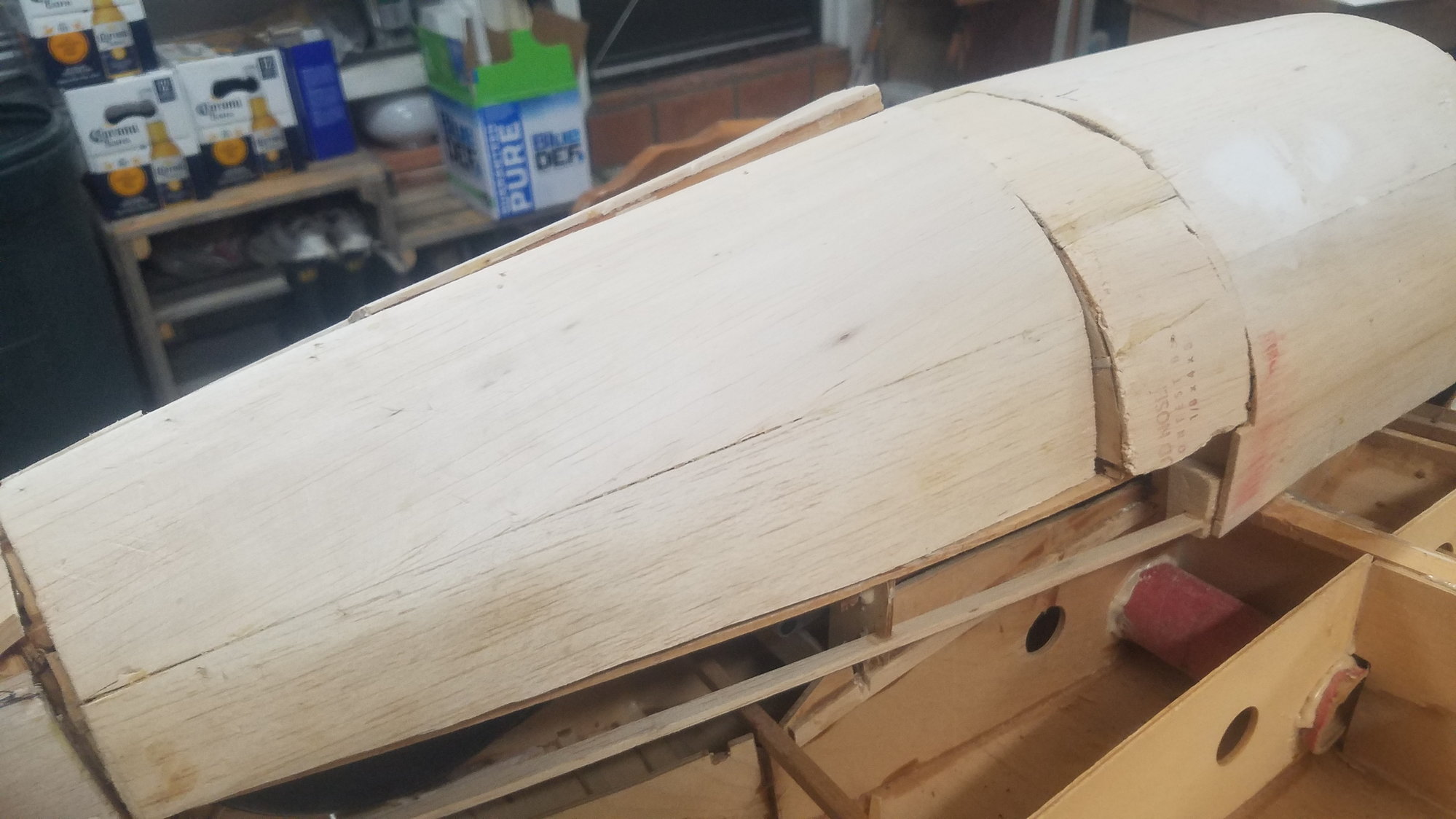
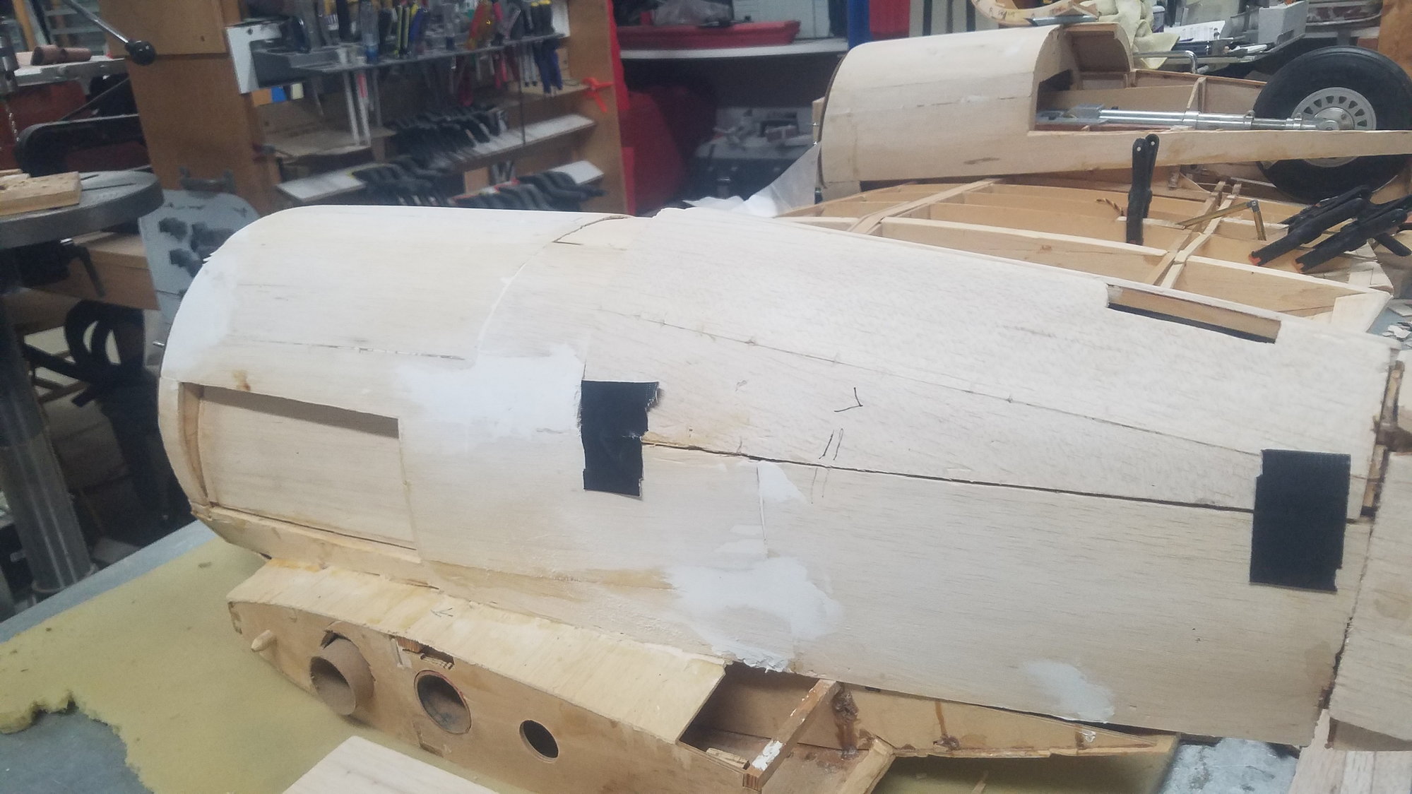
Finished skinning the underside and tail of the fuselage.
If I had to do it again, I would cut smaller strips to go around the tight curves. More seams but better compound curves. I'm guessing 3/8" to 1/2" wide strips with beveled edges.
Left side is the worst for not following the curvature of the fuselage. Not too bad, but not what it should be.
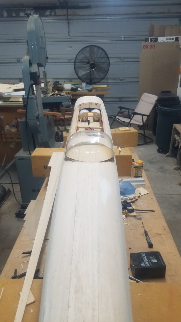
Right side is better. Redid the banding on the turret and now just need to trim it to correct shape

Started work on the central section. trying to figure correct shape for ridge over the wing for each nacelle.
Attached the aileron but will convert my brass linkage to use the plastic push rod method. Reasoning is that brass sliding in brass may create an interference with the radio.
Finished skinning the underside and tail of the fuselage.
If I had to do it again, I would cut smaller strips to go around the tight curves. More seams but better compound curves. I'm guessing 3/8" to 1/2" wide strips with beveled edges.
Left side is the worst for not following the curvature of the fuselage. Not too bad, but not what it should be.
Right side is better. Redid the banding on the turret and now just need to trim it to correct shape
Started work on the central section. trying to figure correct shape for ridge over the wing for each nacelle.
Attached the aileron but will convert my brass linkage to use the plastic push rod method. Reasoning is that brass sliding in brass may create an interference with the radio.
07-09-2022, 07:28 PM
#95
Senior Member
Thread Starter
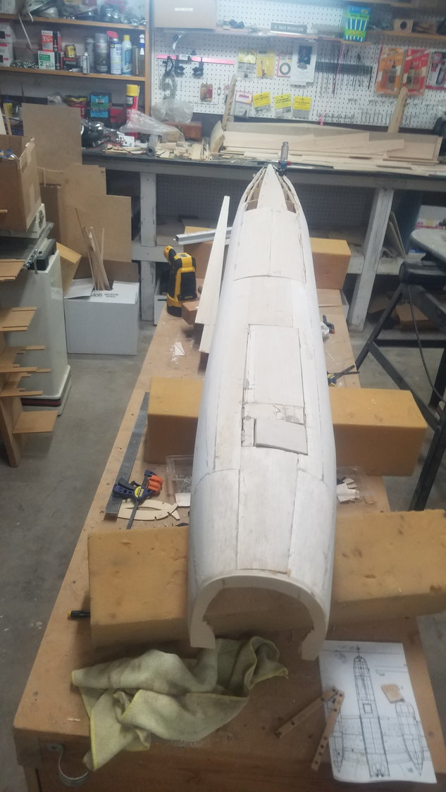
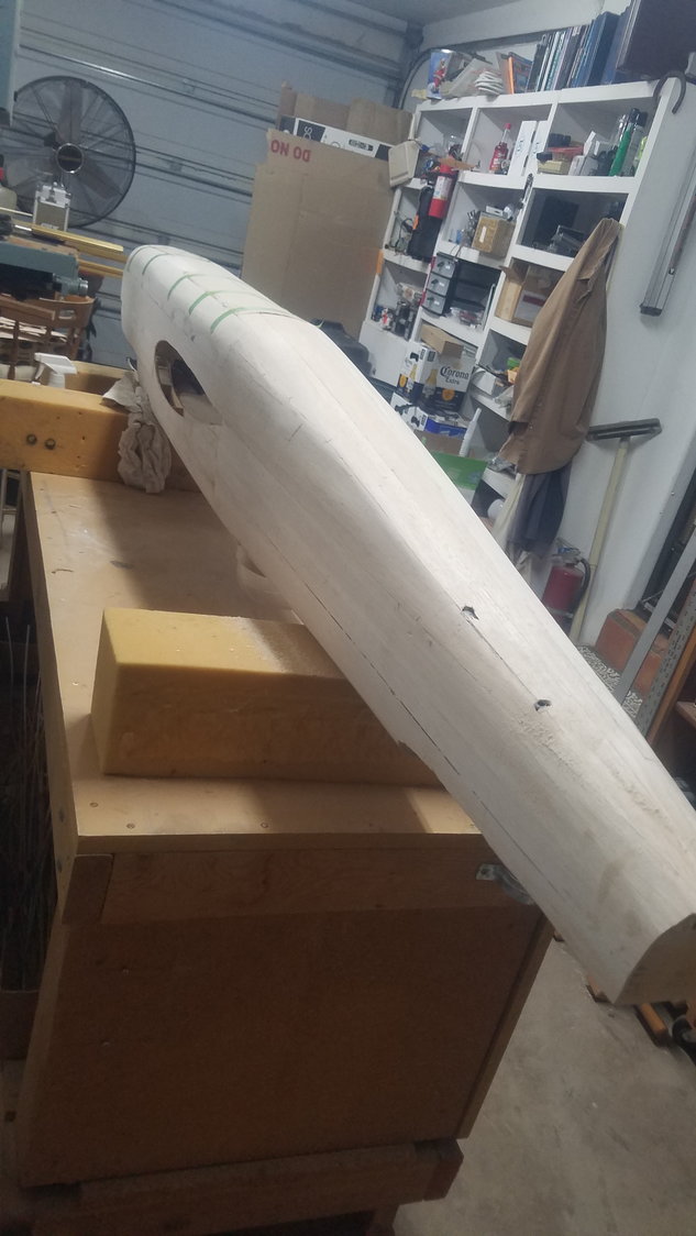
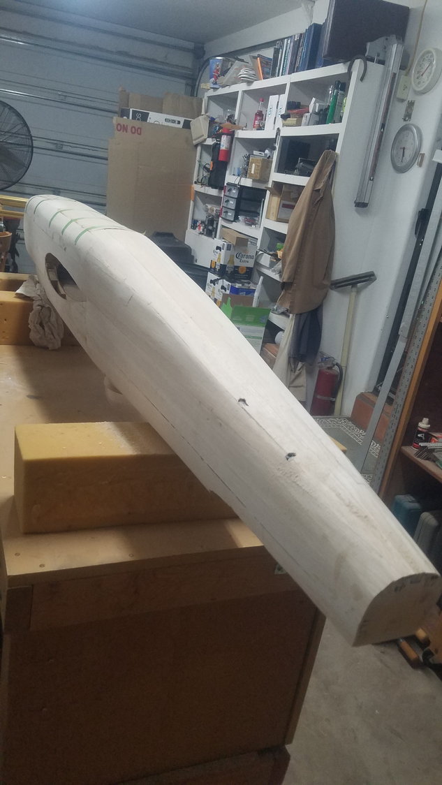
Top side skinned
Bottom side skinned
Need some finished sanding to be complete. Found some very thin original skin so replaced it with a patch.
07-10-2022, 04:45 PM
#96
Senior Member
Thread Starter
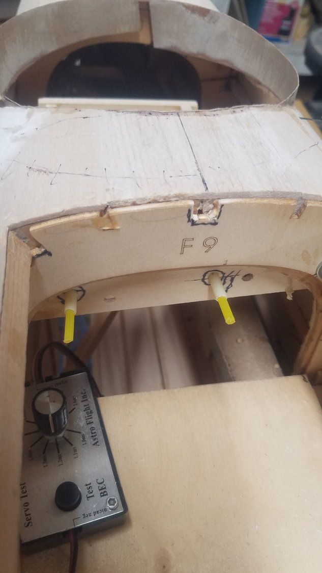
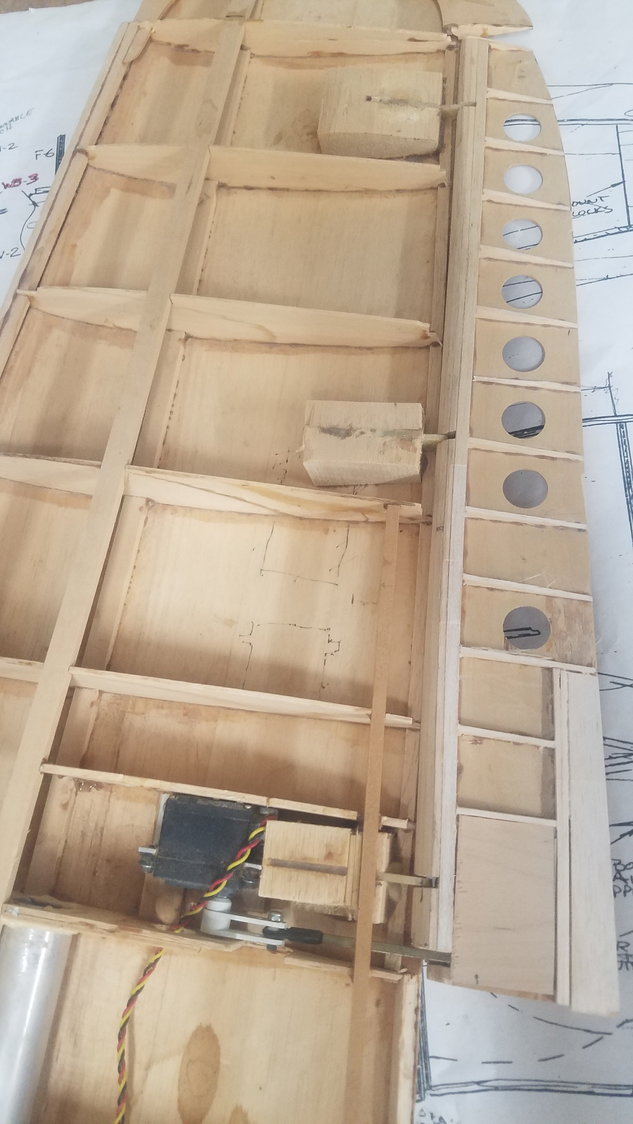
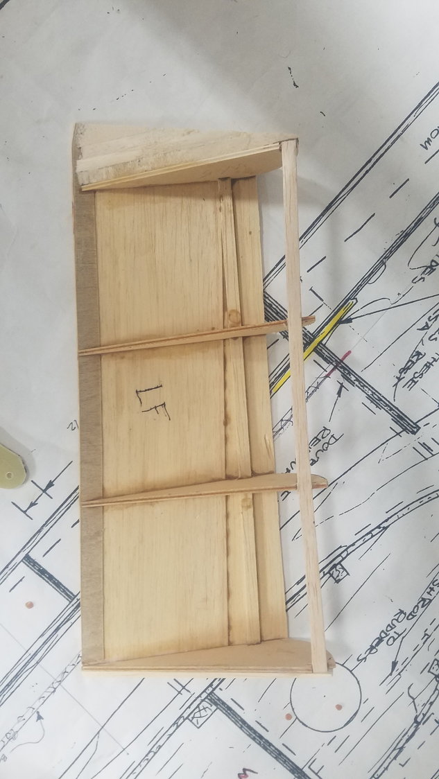
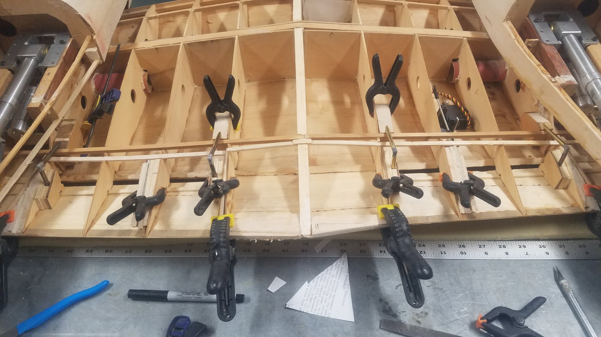
Center section (inboard) flap rebuilt, and servo linage control attach point created. Linkage is in temp location until I find where the servo will mount best in the center section.
Same setup on the other inboard flap. After way too many years setting stored most of all the ribs were damaged or missing. As mentioned before, this is a semi fowler setup so tomorrow I will add the blockage for the brass tube extension for the hinge.
Outboard flaps were in really bad shape. Also had to design the fowler method to match the inboard flaps.
Control attach points were designed for fowler method and flap basically rebuilt. Still will need work on area were the flap meets the center section.
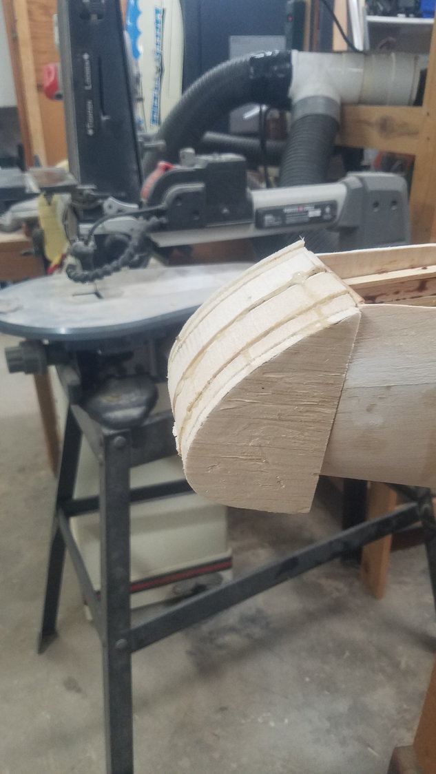
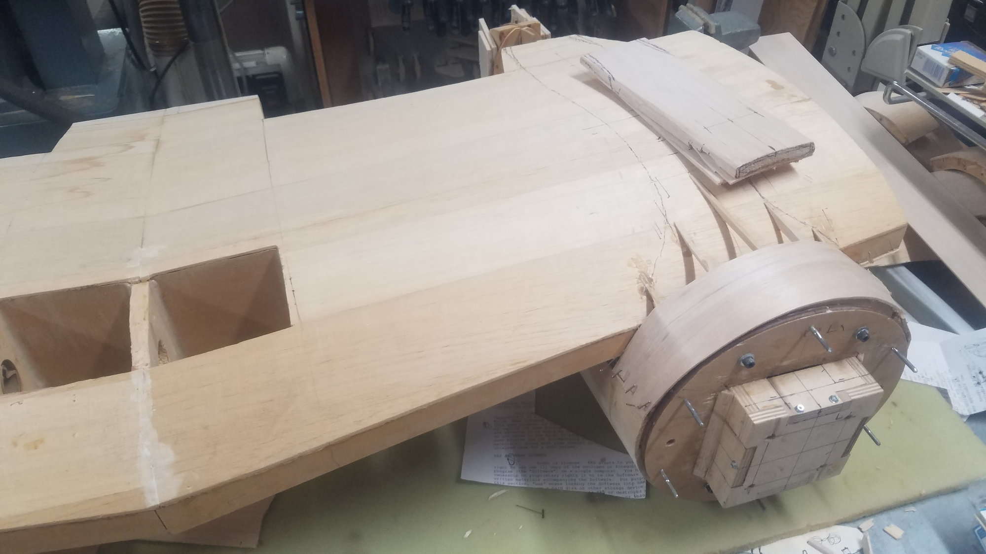
Massive balsa block created and glued on. This is a B model 25 so no gun position here.
A lot of balsa to be cut away to get correct shape.
Aileron in position and have decided to use the sliding square brass tube as I originally designed as it is way too much rework to use the plastic push rod method.
Better shot of servo brass tubes setup. Need to get lighting system ordered and installed and flap servo installed before I can finish closing the wing.
Last edited by rossmick; 07-10-2022 at 07:03 PM. Reason: Correct spelling
07-12-2022, 06:49 PM
#97
Senior Member
Thread Starter
The nacelle and main gear doors are in terrible shape. Not sure why I did what I did, but there is a lot of rework to do on the doors. Gear remounted and now the doors will not close over them. Looks like the doors have warped over all the years setting on the shelf.
Reworking the inner flap to make them fit.
This is the hinge setup for the fowler motion. This will be tested once temporally installed. This will be interesting to get the correct motion to match the outer flaps to the inner ones.
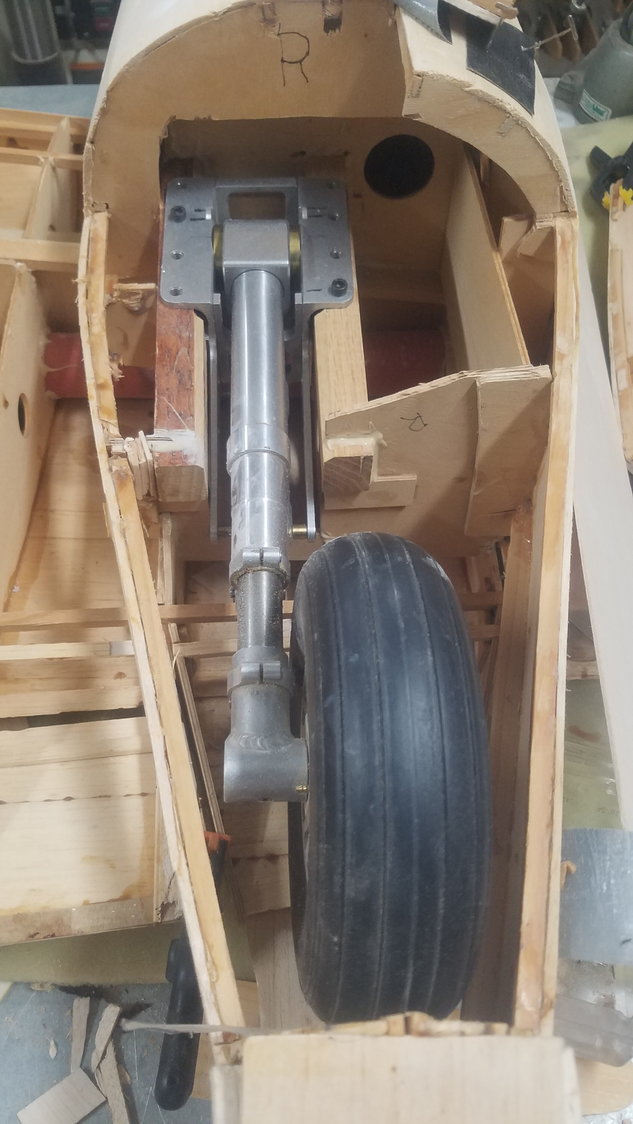
Right main gear temporally installed for gear door install.
Another photo of the Serria Giant gear which has been put back to air from electric. Scale wheel has air powered brakes as well.
The right-hand doors no longer fit and will need a lot of work to get them to work correctly. Looks like the large door has warped. It will be interesting to fix them.
Left-hand gear doors are a mess as well.
Small left door is the best fit of all the doors. Still slightly warped.
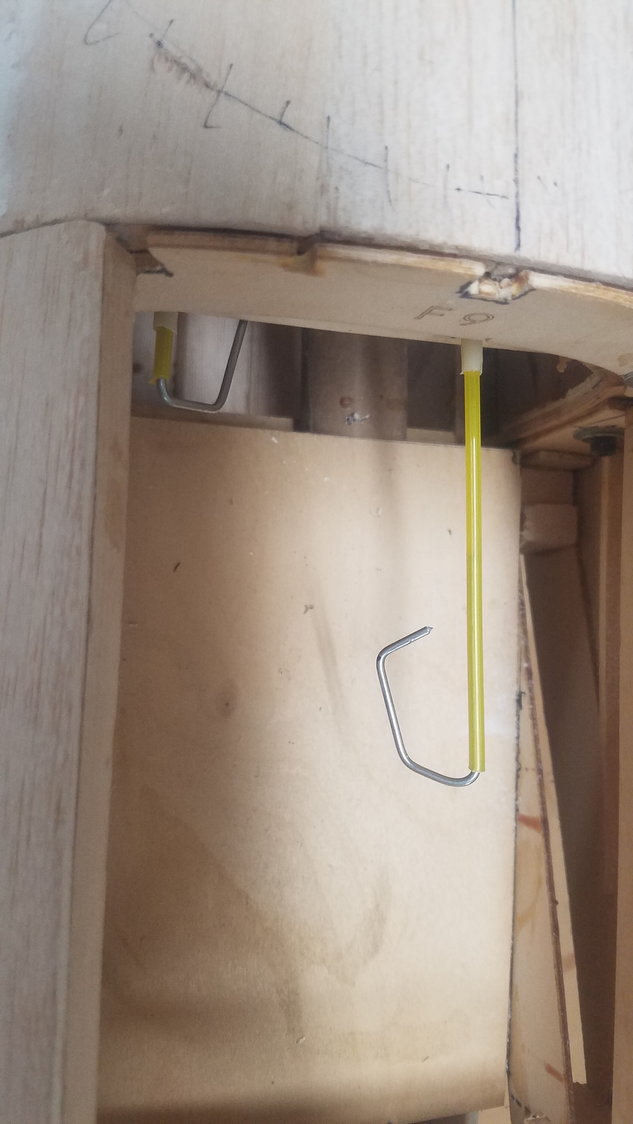
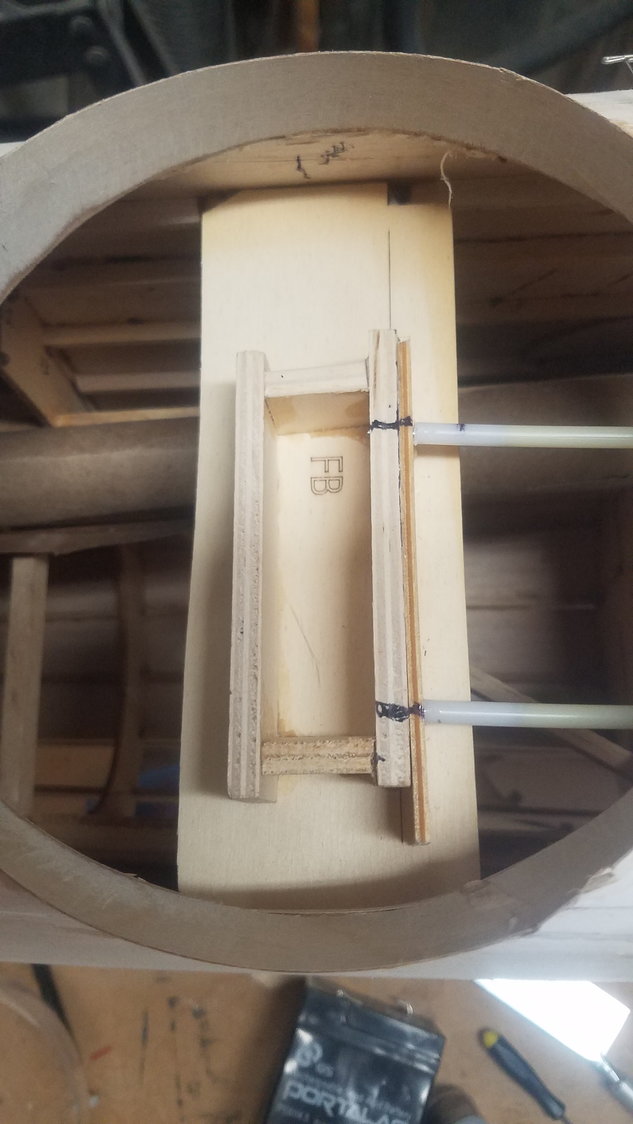
The restraining setup to hold the turret in position. Once pushed in, the wire hooks under the former to keep the pin in place.
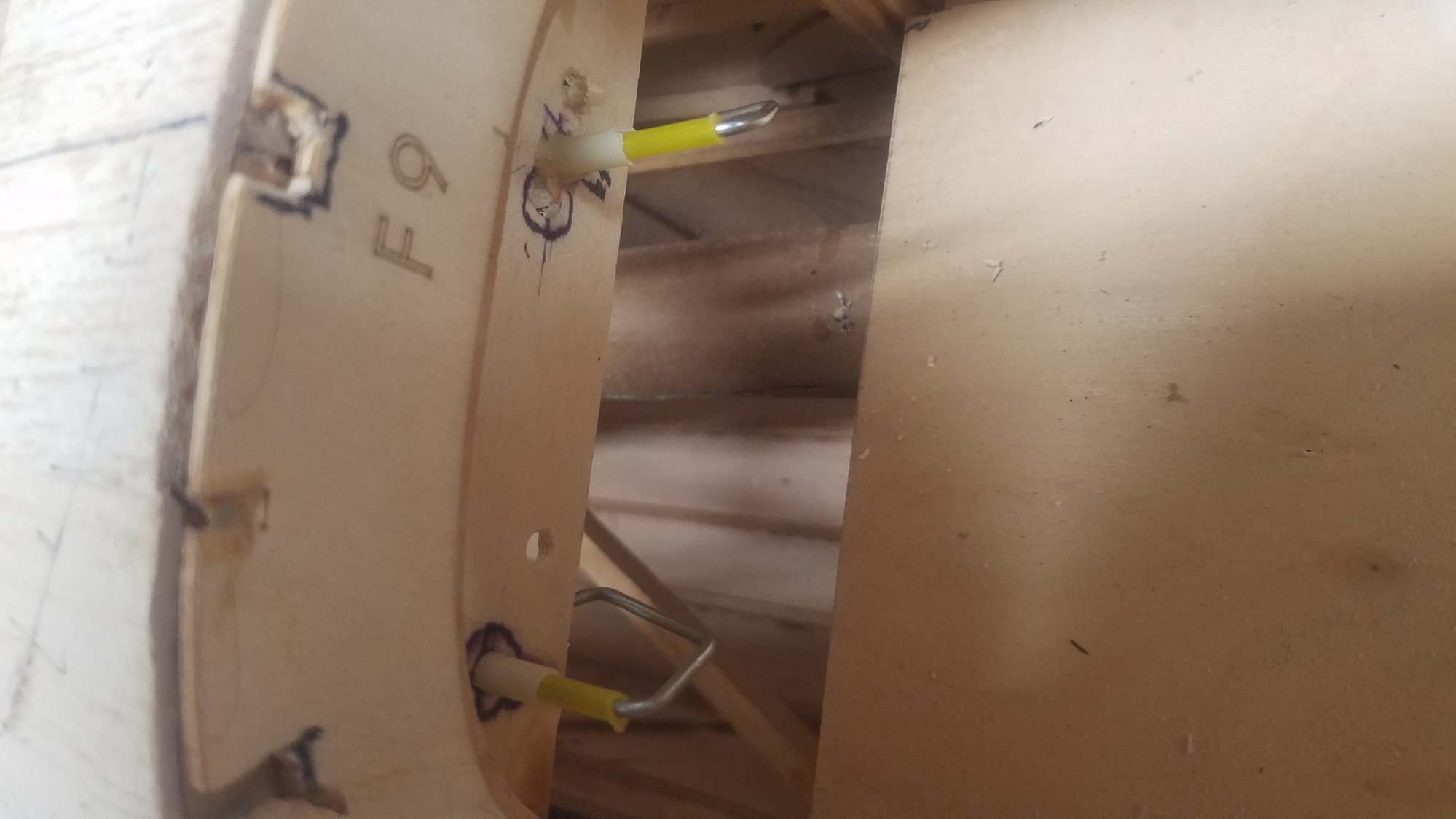
Restraining pins in place and hooked up.
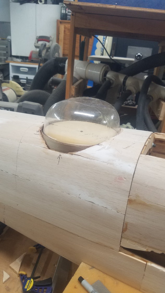
Turret install mostly complete other than filler around the base. I will, in the future, build the gun setup, maybe I can find a kit for the turret.
Reworking the inner flap to make them fit.
This is the hinge setup for the fowler motion. This will be tested once temporally installed. This will be interesting to get the correct motion to match the outer flaps to the inner ones.
Right main gear temporally installed for gear door install.
Another photo of the Serria Giant gear which has been put back to air from electric. Scale wheel has air powered brakes as well.
The right-hand doors no longer fit and will need a lot of work to get them to work correctly. Looks like the large door has warped. It will be interesting to fix them.
Left-hand gear doors are a mess as well.
Small left door is the best fit of all the doors. Still slightly warped.
The restraining setup to hold the turret in position. Once pushed in, the wire hooks under the former to keep the pin in place.
Restraining pins in place and hooked up.
Turret install mostly complete other than filler around the base. I will, in the future, build the gun setup, maybe I can find a kit for the turret.
07-13-2022, 04:40 PM
#98
Senior Member
Thread Starter
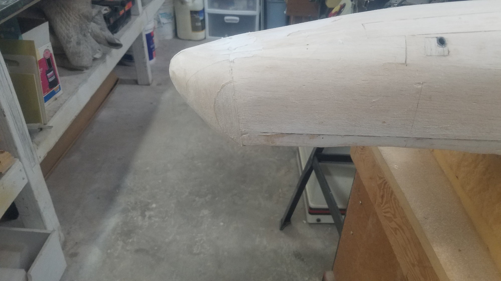
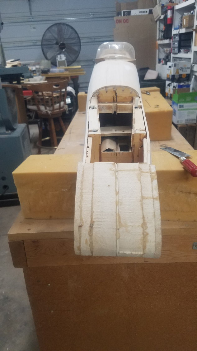
Sanded out the tail cone section. A lot of balsa saw dust.
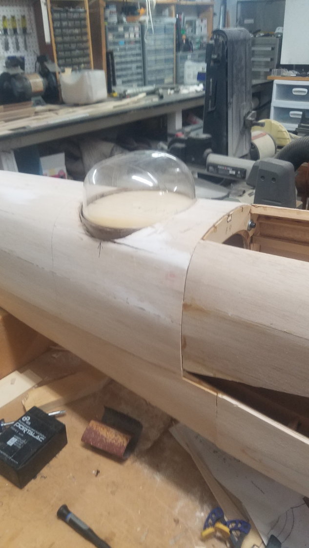
The actual B model tail cone tip is a clear plastic cone. I am just going to simulate the plastic area and add the two false broom stick guns that Dolittle stuck on to keep fighters back. They even painted black strips to make it look like gun slots. I wonder if it actually worked?

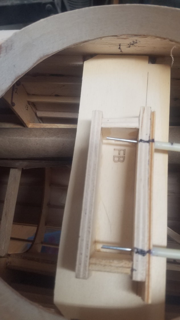
Here is the hinge setup. I will need to drill and pin to make sure the Robart hinge does on pull out of the brass tube. I will glue the hinge in the tube but want to make sure it does not pull loose on flap deployment. Block is standard 3/4" pine, drilled and shaped to fit.
Mounting blocks to hinges and linkage in temporary locations. Setting this up has taken all day and then some.
Brass tube to be glued in plywood keeper. There is a spacer, the keeper, and then an end cap to hold it together.
Hinge rotation point drawn out on plans and dimensions held from hinge to hinge. Location and height are critical to get the flap to work correctly.
Here it is all assembled as dry fit. This was a very large project attempting to be more scale. It would have been much simpler to just do a standard hinge as per the plan. Installing the servos is next. It will be interesting to see what happens when the flaps are deployed for the first time with plenty of altitude. After installing the servos, will do the outer flaps to match, could be tricky.
07-14-2022, 04:53 PM
#99
Senior Member
Thread Starter
Decided to recheck the dimensions after watching a walk around video on the 25. Scale wise, the dimensions were pretty close but somewhat long. I have now documented the dimensions and setup gauges to set the hinges. The problem comes from having to go over the top of the spruce 1/4" bottom rear spar. I'm feeling much more confident that these dimensions will work. Went ahead and installed the servo linkage and skinned the flaps, photos tomorrow.
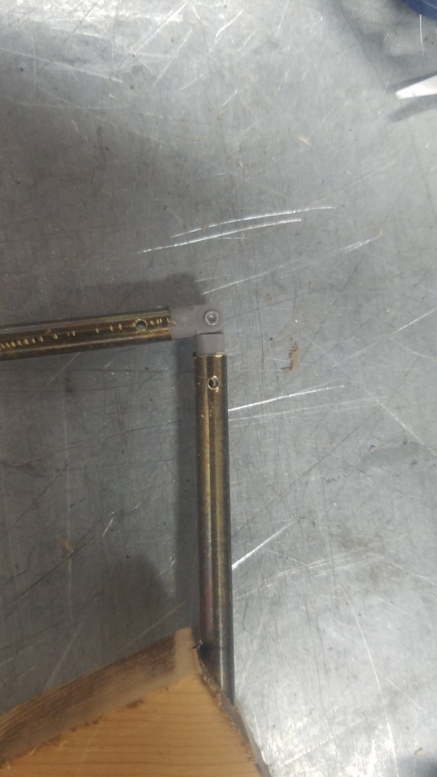
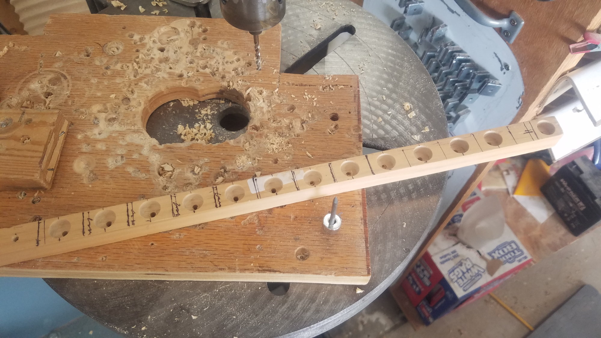
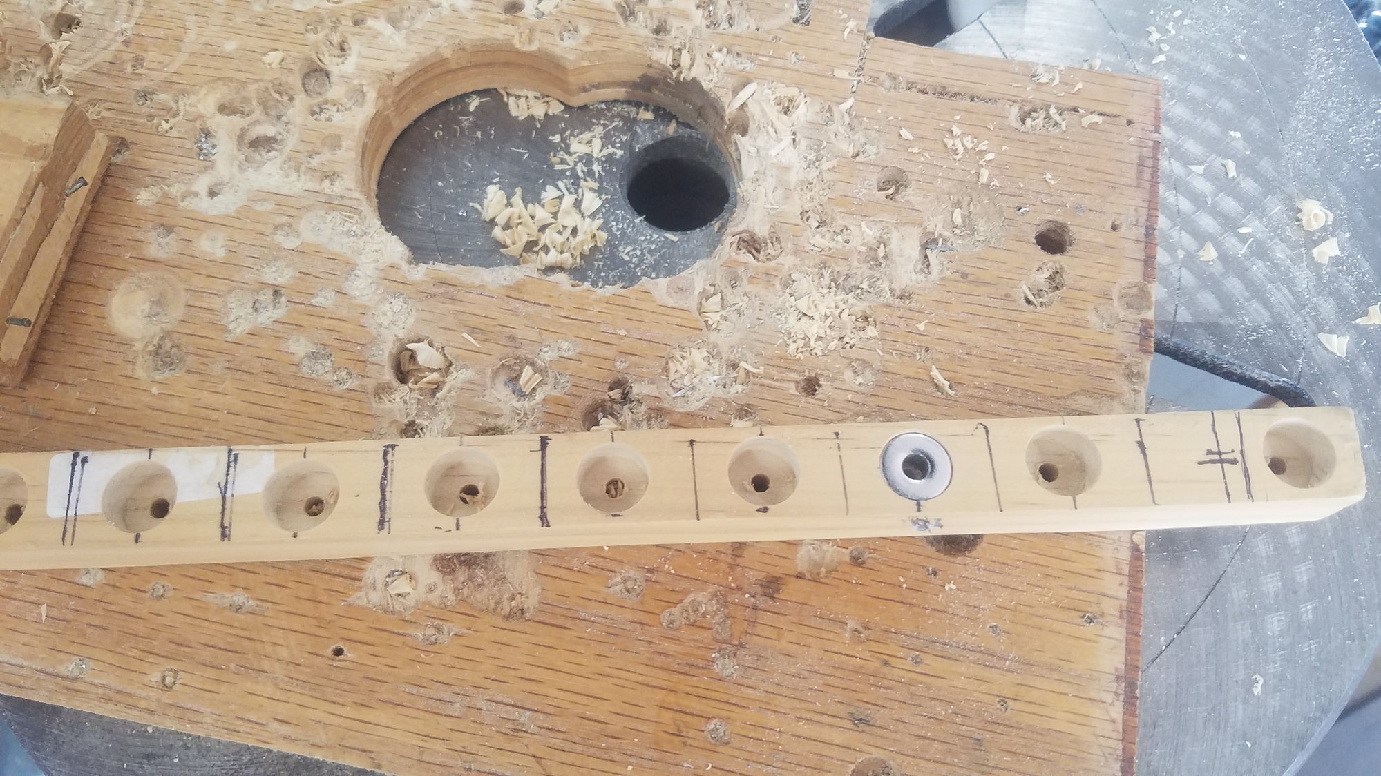
Drilled the brass tubes to keep the Robart hinge from pulling out. Chucked up the very small bit with just 1/4" of it sticking out to accomplish the drilling in the drill press.
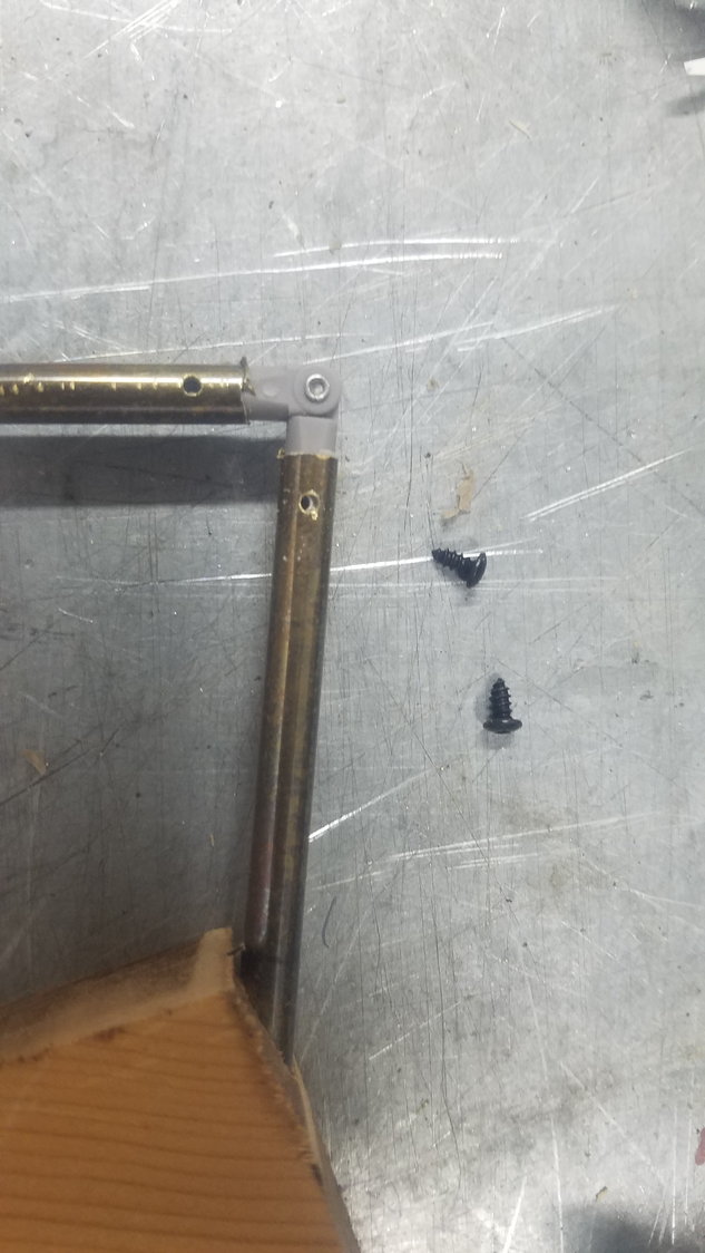
Show the very small button head screws that were selected.
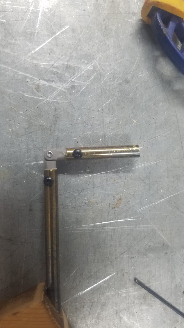
Screws installed and I am confident that the linkage will not come apart. Slow but critical work.
Drilled the brass tubes to keep the Robart hinge from pulling out. Chucked up the very small bit with just 1/4" of it sticking out to accomplish the drilling in the drill press.
Show the very small button head screws that were selected.
Screws installed and I am confident that the linkage will not come apart. Slow but critical work.
Last edited by rossmick; 07-14-2022 at 04:55 PM. Reason: Spelling
07-15-2022, 07:37 PM
#100
Senior Member
Thread Starter
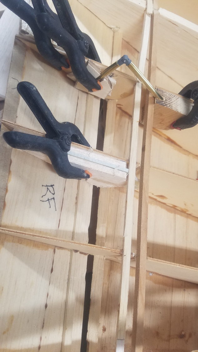
Changed from a drilled 3/4" block to the same sandwich technique used in the flap. This also allowed for a larger, stronger bond to the rib and wing.

This sandwiched approach allowed for more ability to set the correct angle and location. Temporary spacers in place to set location of flap.
Right flap. Each hinge location was slightly different and the sandwich of 2 spacers, the slotted hinge arm holder and then the end cap allowed a stronger and more manageable arrangement.
Left flap. Elected to not glue Robart hinge in the brass tubes and just use the set screw. This allows for removal and adjustment if necessary.
Temporary gauge to set correct height. Tomorrow will use Aeropoxy on hinge section in the flap after shaping flap to miss the Nacelle and inner section.
Last edited by rossmick; 07-15-2022 at 08:24 PM. Reason: Correction