


CARF-Models Mig 17 build thread
 03-25-2022, 12:25 PM
#51


 03-25-2022, 02:38 PM
#53
Senior Member
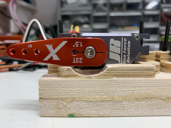
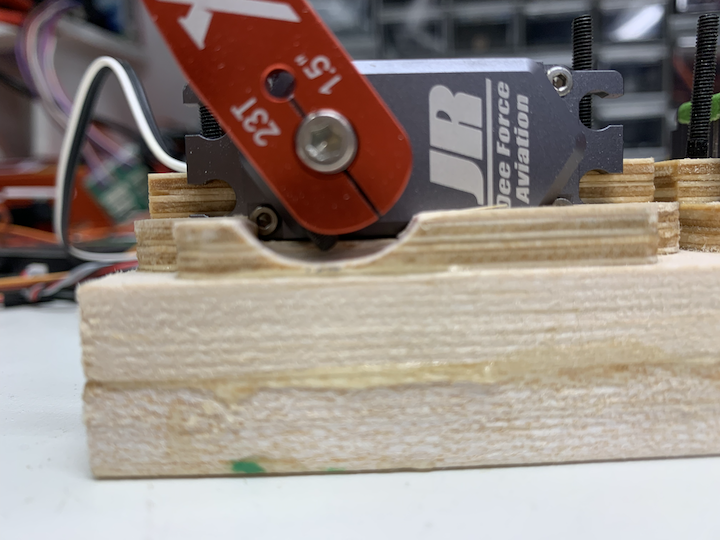
1. This is a high performance turbine. Without the part the servo is meant to be in, a better alternative than double sided tape is needed.
2. Gyro stabilized at 100 mph plus, that servo is going to be twitching almost constantly in anything but absolutely calm air. The tape will hold heat in the servo potentially causing failure.
3. I've never had much luck using double sided tape for long on anything but an absolutely smooth surface, so unless the inside if the servo cover is as smooth as the visible side, its going to come loose.
4. Mounting it in that matter puts all the stress of the servo unit, not on the supporting structure where it is meant to be, but on the screws holding the servo cover in place. These screws are fine for holding the servo cover, but when you add in the stress of holding the servo as it moves the linkage, it will overstress the screws, causing them to posblbly break or strip.
Instead, if the servo frame was missing from the kit, either wood blocks, or aluminum angle, cut to fit in the space provided, using the existing mounting holes, would be a better option if the poster did not want to wait for replacements from CARF.
Does this clarify my post for you better, Dave? Happy now?
Last edited by Txmustangflyer; 03-25-2022 at 02:41 PM.
The following users liked this post:
Marcinek (03-25-2022)
03-25-2022, 09:19 PM
#54

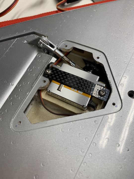
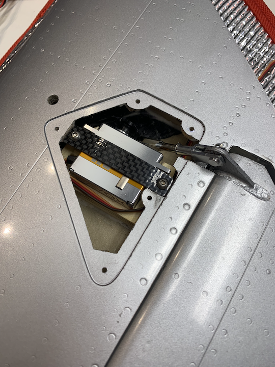
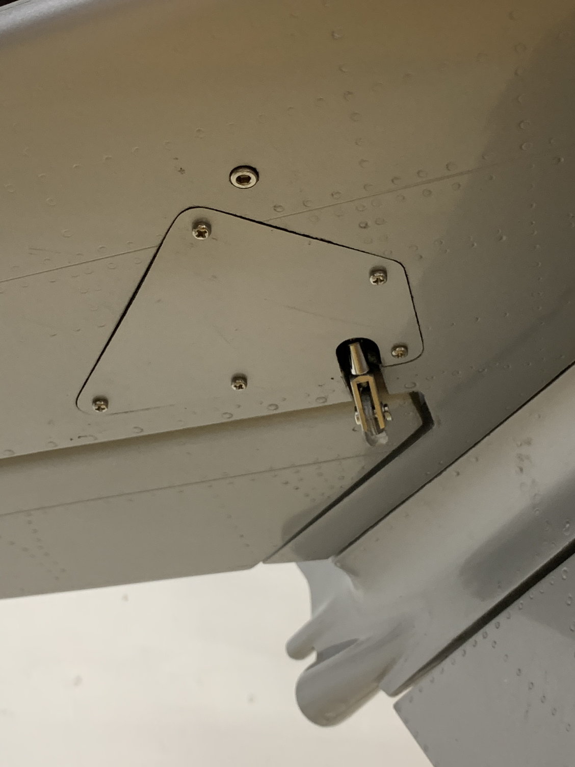
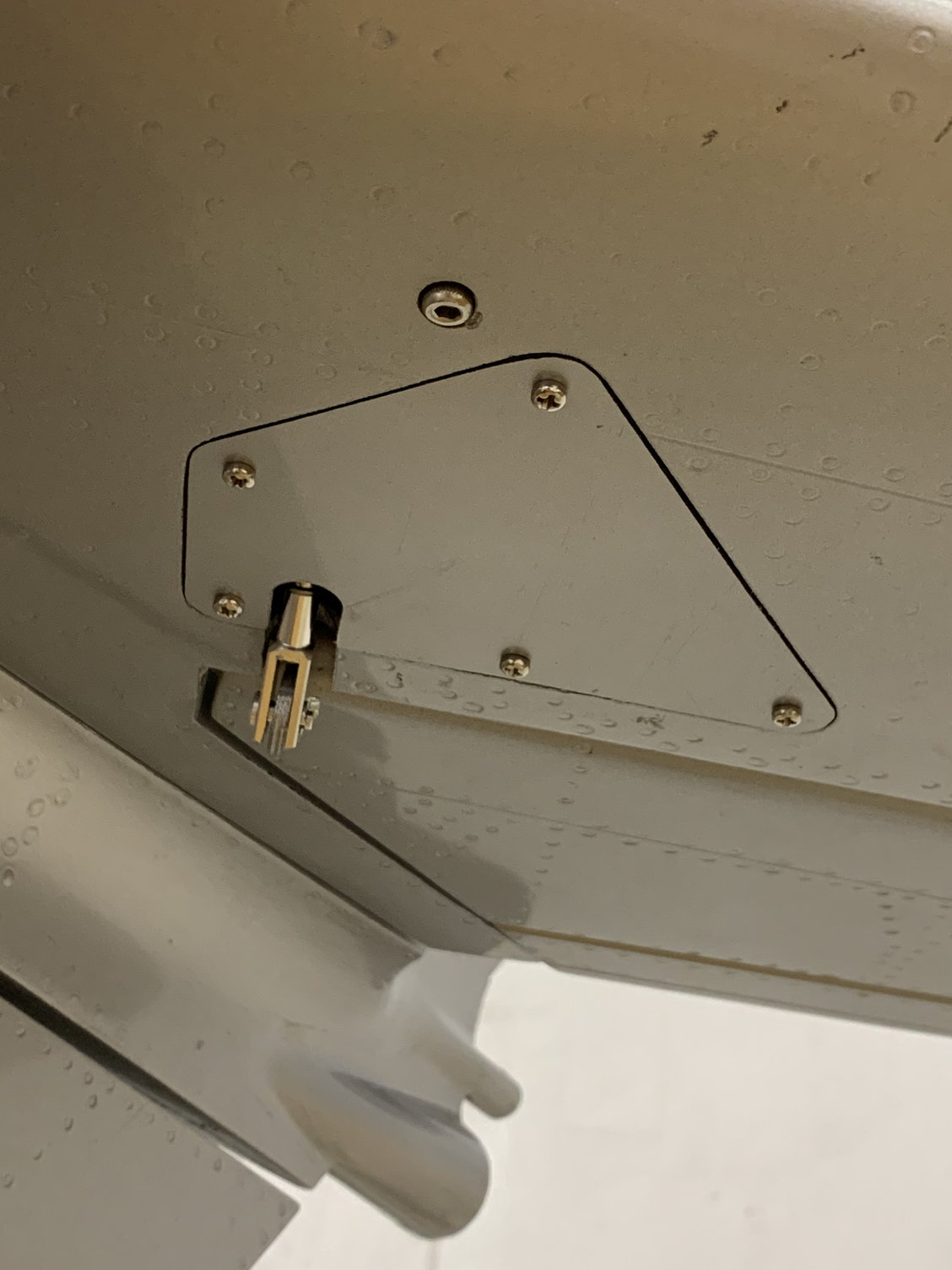
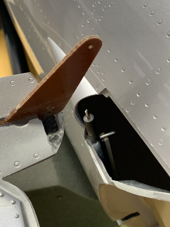
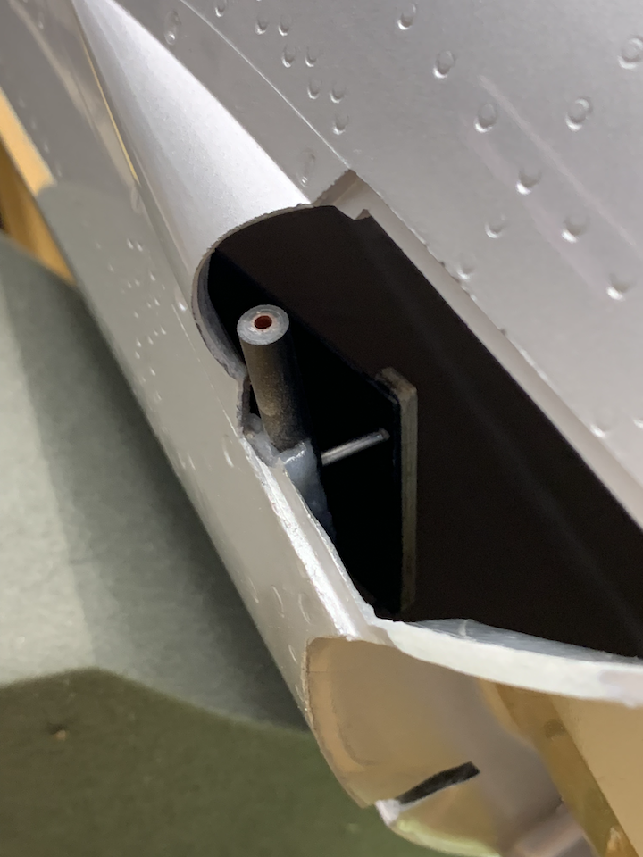
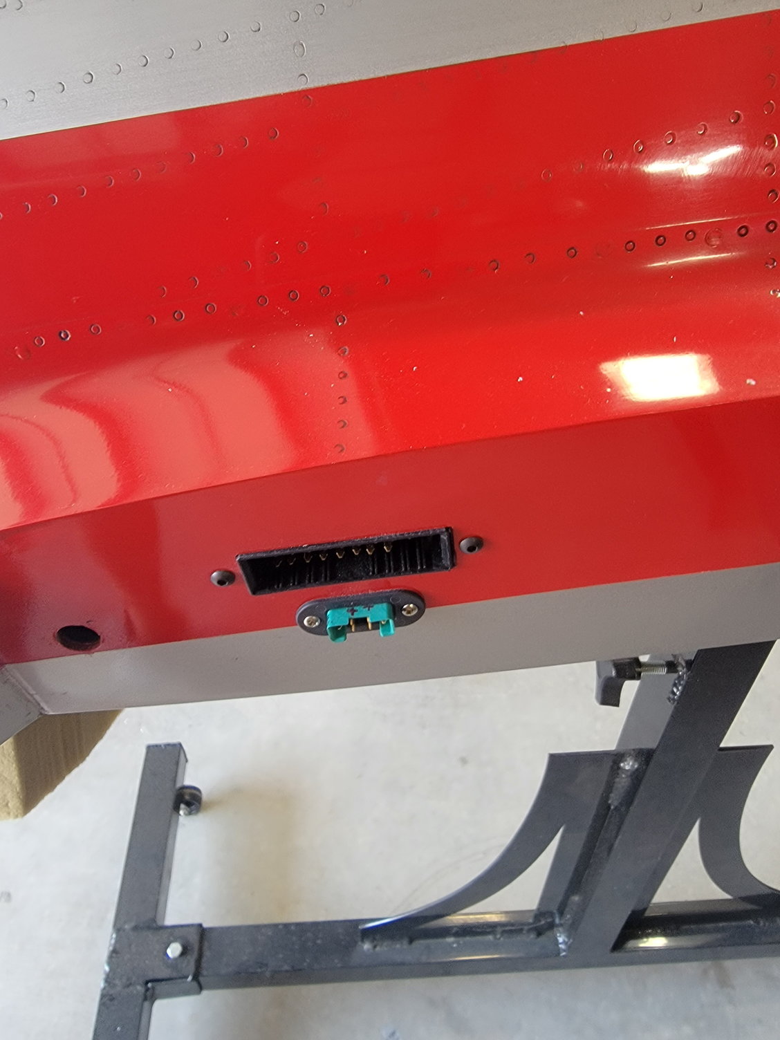
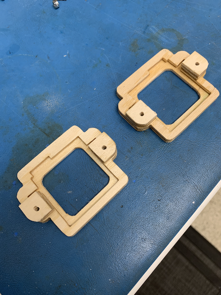
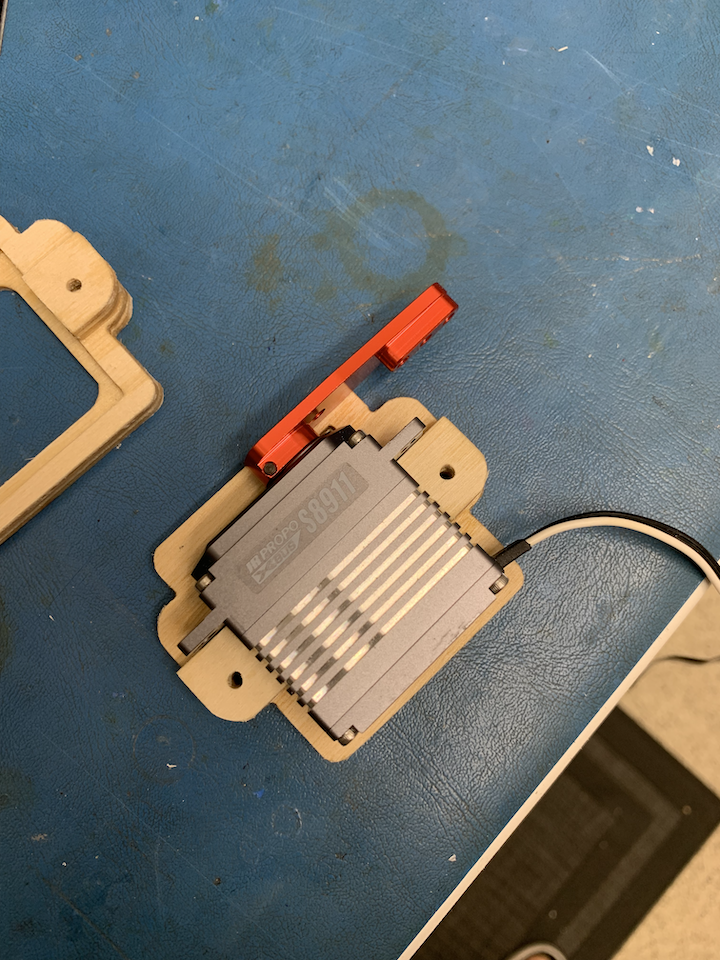
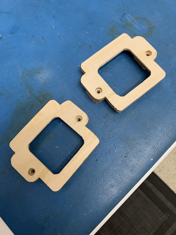
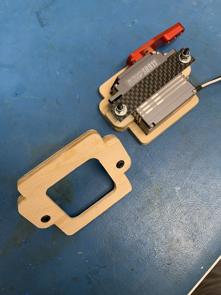
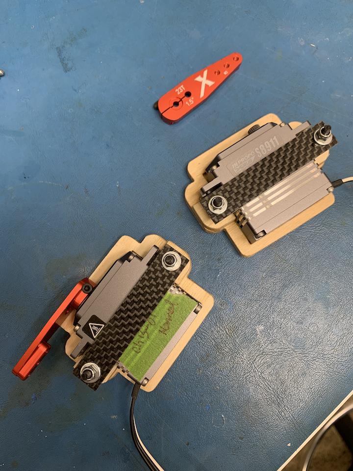
Thanks for the comments guys. So I finished up the left and right elevators. Took a closer look at what I had to work with and decided to steal the two carbon fiber pieces from the front fuselage pack and install them over the servos. Needed to file away some of the plywood to get them to fit properly. Overall I think this will work and the covers go on fairly flush. I found some extra carbon fiber strips from another project that I will cut to size and use them for nose gear door servos when I get to them. Here are some pictures of the elevators assembled:
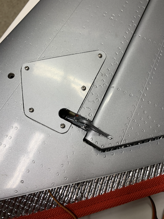
Left Cover
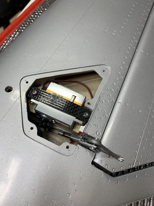
Left Servo (View 1)
Left Servo (View 2)

Right Servo (View 1)
Right Servo (View 2)
Right Cover
Left Cover
Left Servo (View 1)
Left Servo (View 2)
Right Servo (View 1)
Right Servo (View 2)
Right Cover
The following users liked this post:
Halcyon66 (03-25-2022)
03-25-2022, 11:37 PM
#55
Thread Starter
What you have done was the original design idea, on the prototypes the space was a bit limited for the strap, maybe they have found some space with a different layup. Double sided tape is not the idea or solution, but a spacer on the stiff hatch is all that was required to stop the servo lifting. The frame takes most of the load and there is not much load spread over the screws.
CARF’s only failing is not getting the manual out with these early kits to show what was intended. (then we all know that modellers go their own way many times-particularly in Europe)
CARF’s only failing is not getting the manual out with these early kits to show what was intended. (then we all know that modellers go their own way many times-particularly in Europe)
03-25-2022, 11:58 PM
#56
Seriously.....................................
"Stop posting what you don�t know about�
The mounting method is correct, I do recommend a wood shim between the hatch and servo case, but the ply frame gives ample support, yiu can watch videos of the Migs flying to prove it."
Now your saying that it was the way they were going to do it in the first place. Yet (as per usual CARF has no manual, normally no landing gear) your now framing the thread to cover the short falls.
So WHAT was the point of your post having a go at Txmustangflyer when he was dead on the mark.
Man it never ends, nothing more than endless infomercials.
Regards,
03-26-2022, 02:09 AM
#57
Senior Member
Worse, not even an apology.
That sews it up..CARF won't see a red cent of my hard-earned. Not even for a P-51
That sews it up..CARF won't see a red cent of my hard-earned. Not even for a P-51
Last edited by Txmustangflyer; 03-26-2022 at 04:18 PM.
03-26-2022, 08:57 PM
#58
What you have done was the original design idea, on the prototypes the space was a bit limited for the strap, maybe they have found some space with a different layup. Double sided tape is not the idea or solution, but a spacer on the stiff hatch is all that was required to stop the servo lifting. The frame takes most of the load and there is not much load spread over the screws.
CARF�s only failing is not getting the manual out with these early kits to show what was intended. (then we all know that modellers go their own way many times-particularly in Europe)
CARF�s only failing is not getting the manual out with these early kits to show what was intended. (then we all know that modellers go their own way many times-particularly in Europe)
03-26-2022, 09:17 PM
#59
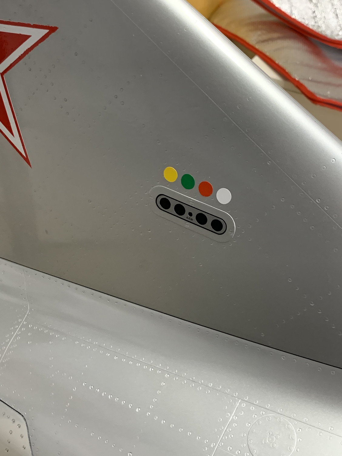
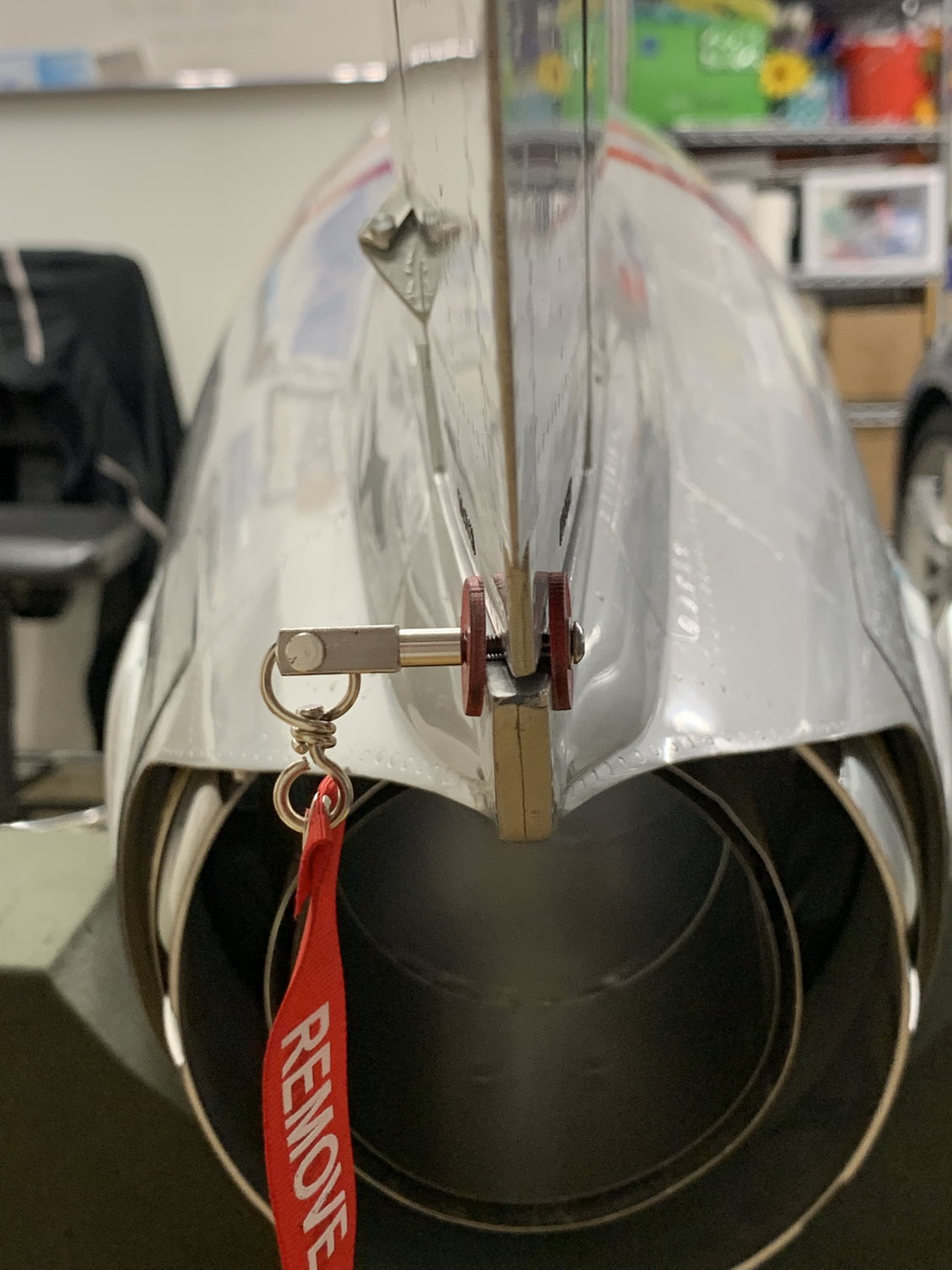
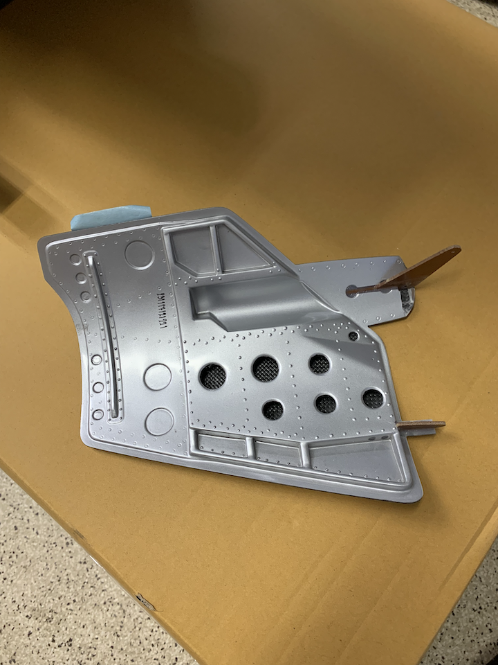
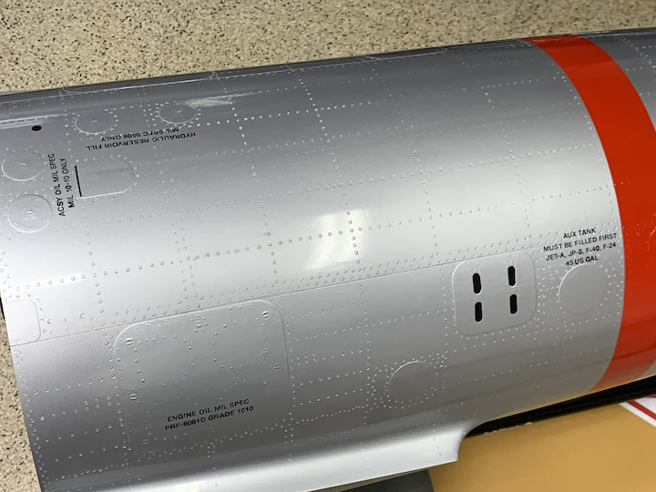
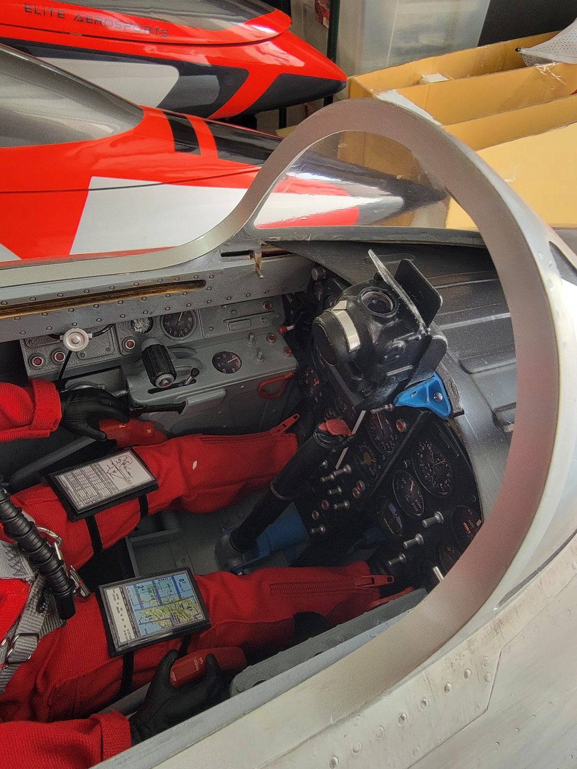
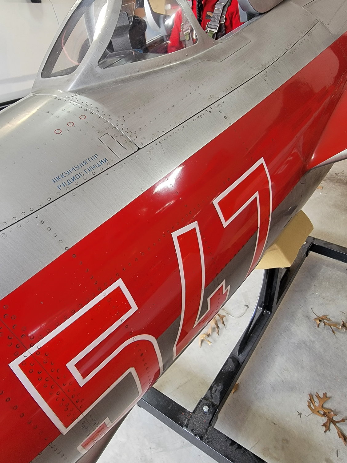
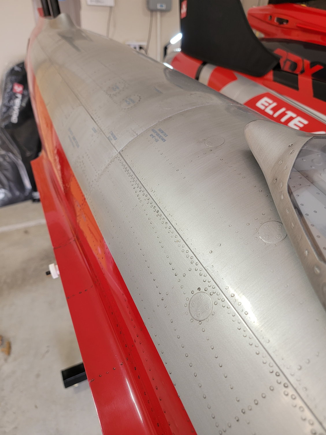
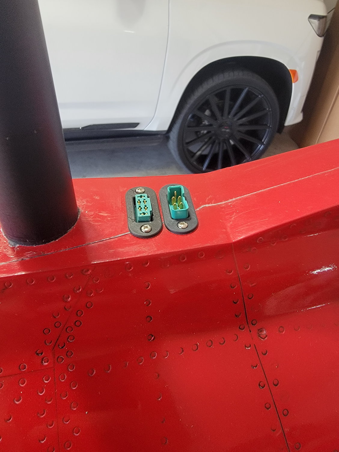
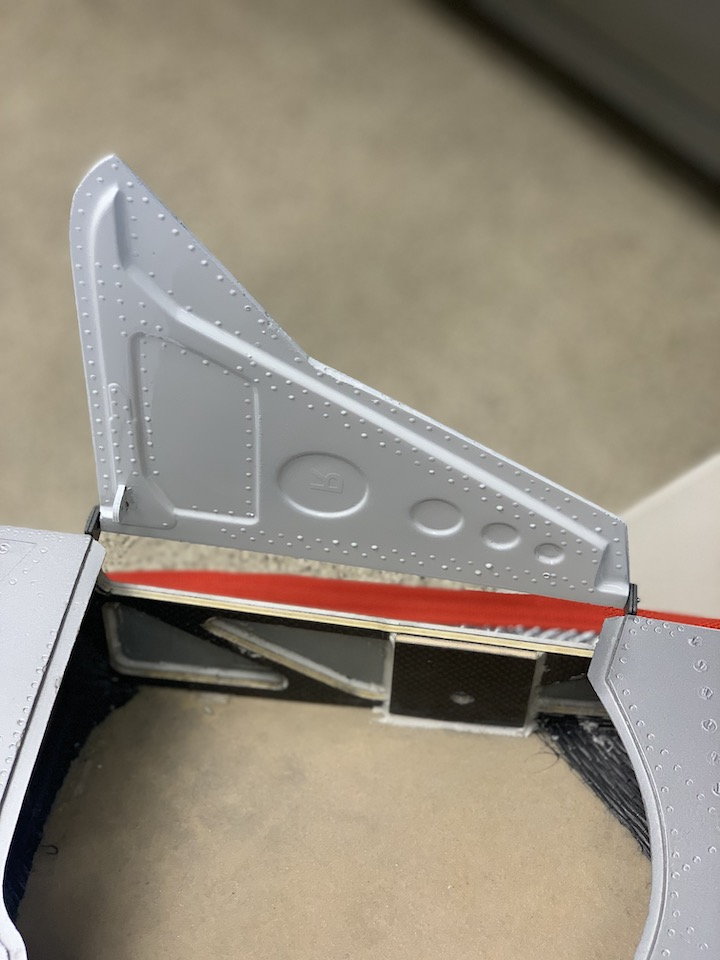
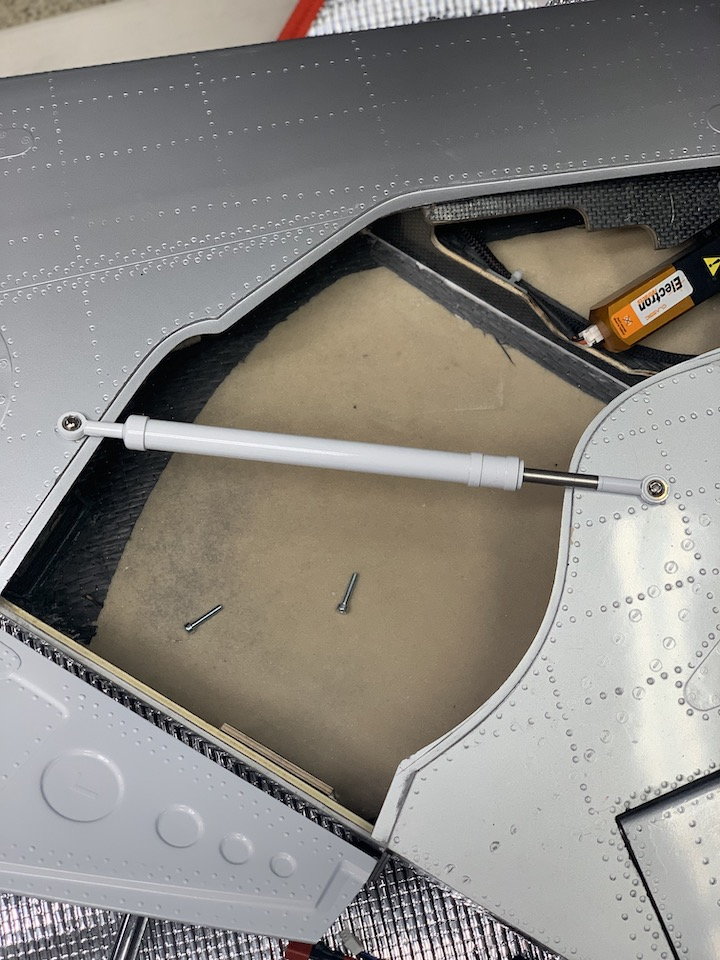
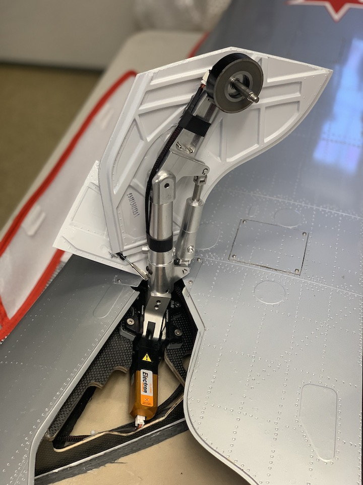
With the elevators done I assembled them to the fin, and then attached it to the rear section of the fuselage to check overall fit. Everything is really tight and also screwed in the hardware to ensure hole alignment. I swapped out the black socket head screws for SS ones to match or blend in with the other hardware. Added some graphic details to the fin and fuse. Had some parts laying around and quickly mocked up the �Remove Before Flight� assembly block that I�ve seen on the real jet. I plan to do a few more of these little details as I go. Here are some photos from today:
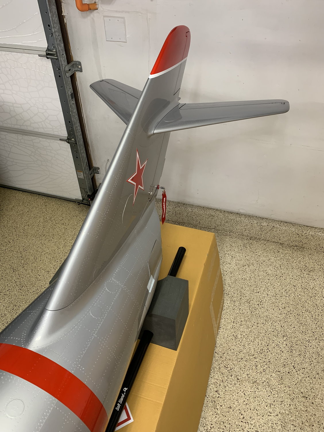
Assembled tail
Flare dispenser
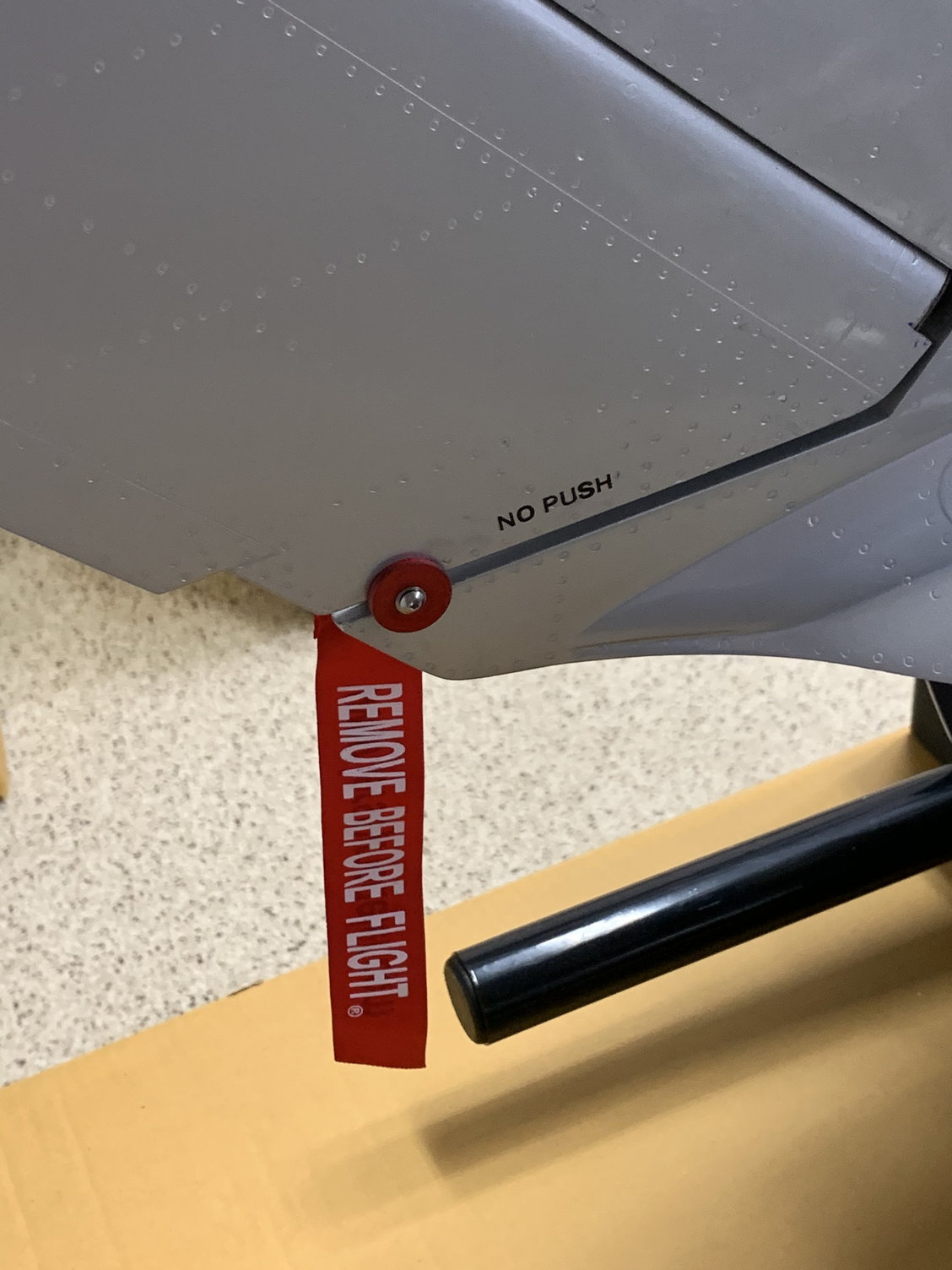
Rudder remove before flight
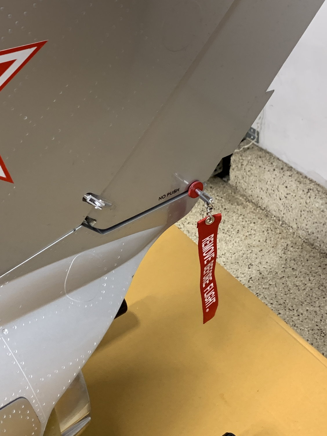
Rudder remove before flight
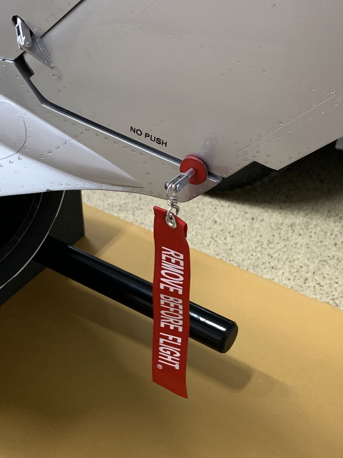
Rudder remove before flight
Rear view
View of the TP
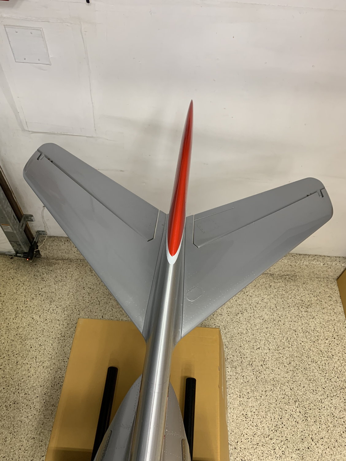
Tail from above
Right elevator cover
Left elevator cover
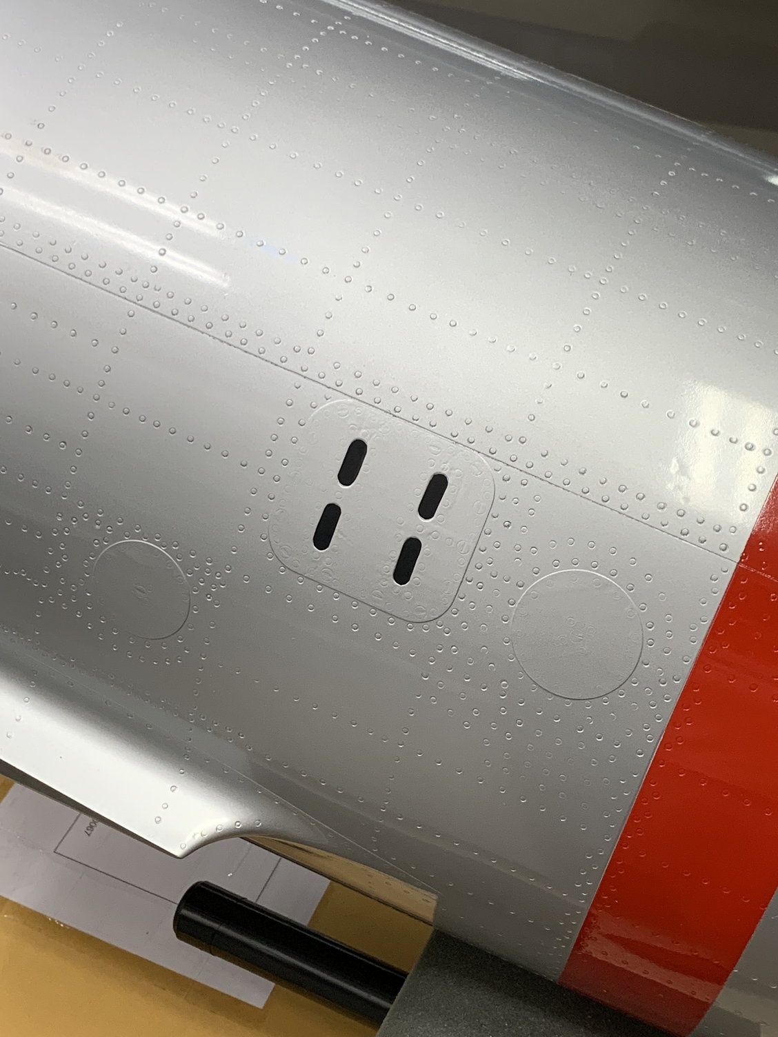
Fuse detail
Fuse detail text
Assembled tail
Flare dispenser
Rudder remove before flight
Rudder remove before flight
Rudder remove before flight
Rear view
View of the TP
Tail from above
Right elevator cover
Left elevator cover
Fuse detail
Fuse detail text
Last edited by Airforce7; 03-26-2022 at 09:26 PM. Reason: Minor text changes
03-28-2022, 06:02 AM
#60
Senior Member
1. Servo cover fitment looks much better.
2. No worrying about the servos coming lose now.
3. Nice detailing.
4. Video the maiden.
5. No shooting down foamie sabres or F4's
6. Fly the paint off of it.
Honestly, CARF still owes you the proper mounting hardware for those servos but how you mounted them will be as good. They'll stay cool enough. And that CF ain't gonna give.
Last edited by Txmustangflyer; 03-28-2022 at 06:08 AM.
03-28-2022, 06:00 PM
#61
1. Servo cover fitment looks much better.
2. No worrying about the servos coming lose now.
3. Nice detailing.
4. Video the maiden.
5. No shooting down foamie sabres or F4's
6. Fly the paint off of it.
Honestly, CARF still owes you the proper mounting hardware for those servos but how you mounted them will be as good. They'll stay cool enough. And that CF ain't gonna give.
2. No worrying about the servos coming lose now.
3. Nice detailing.
4. Video the maiden.
5. No shooting down foamie sabres or F4's
6. Fly the paint off of it.
Honestly, CARF still owes you the proper mounting hardware for those servos but how you mounted them will be as good. They'll stay cool enough. And that CF ain't gonna give.
 03-28-2022, 06:28 PM
#62
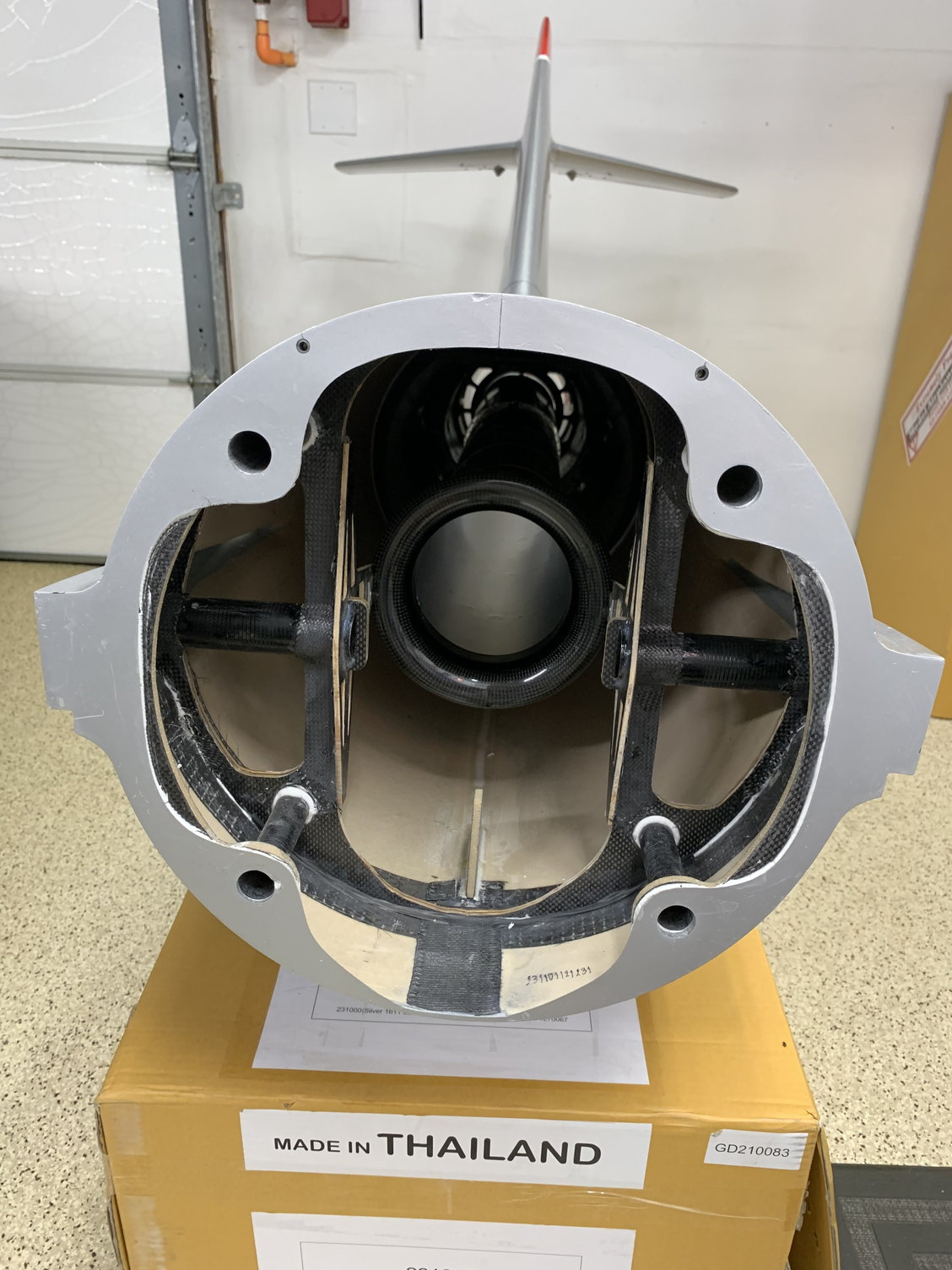
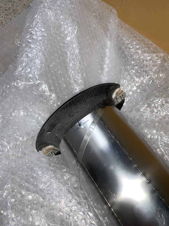
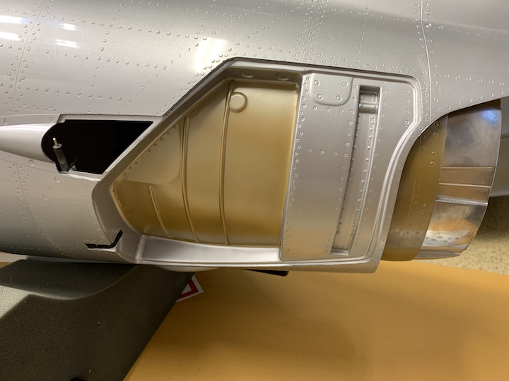
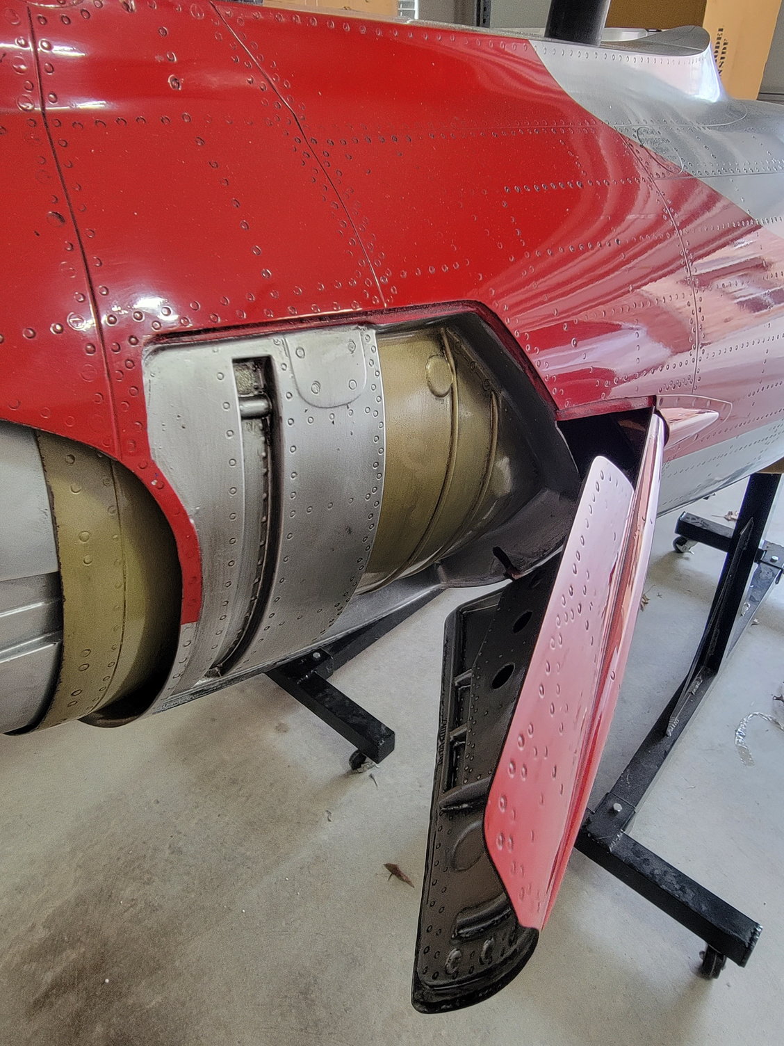
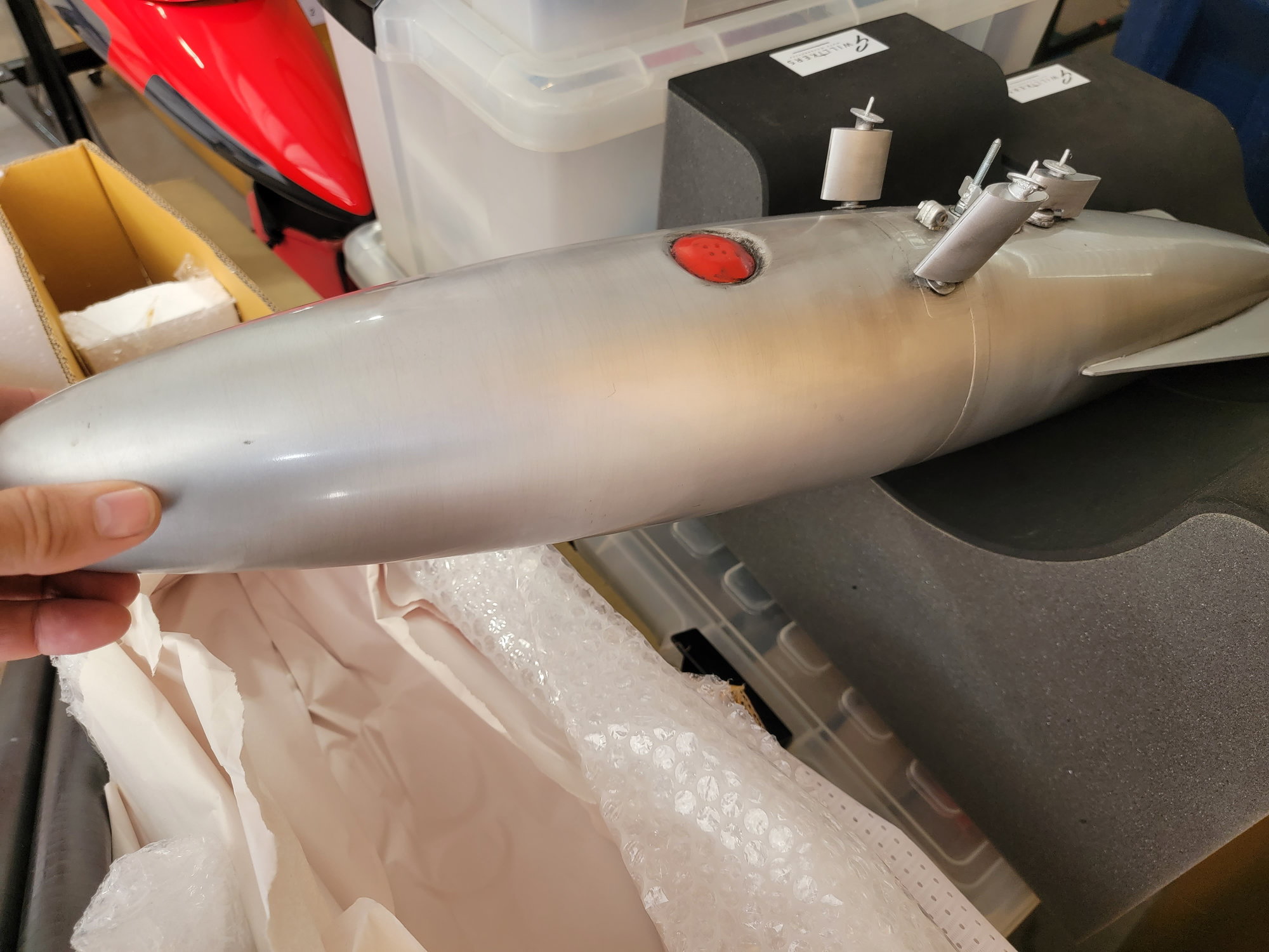
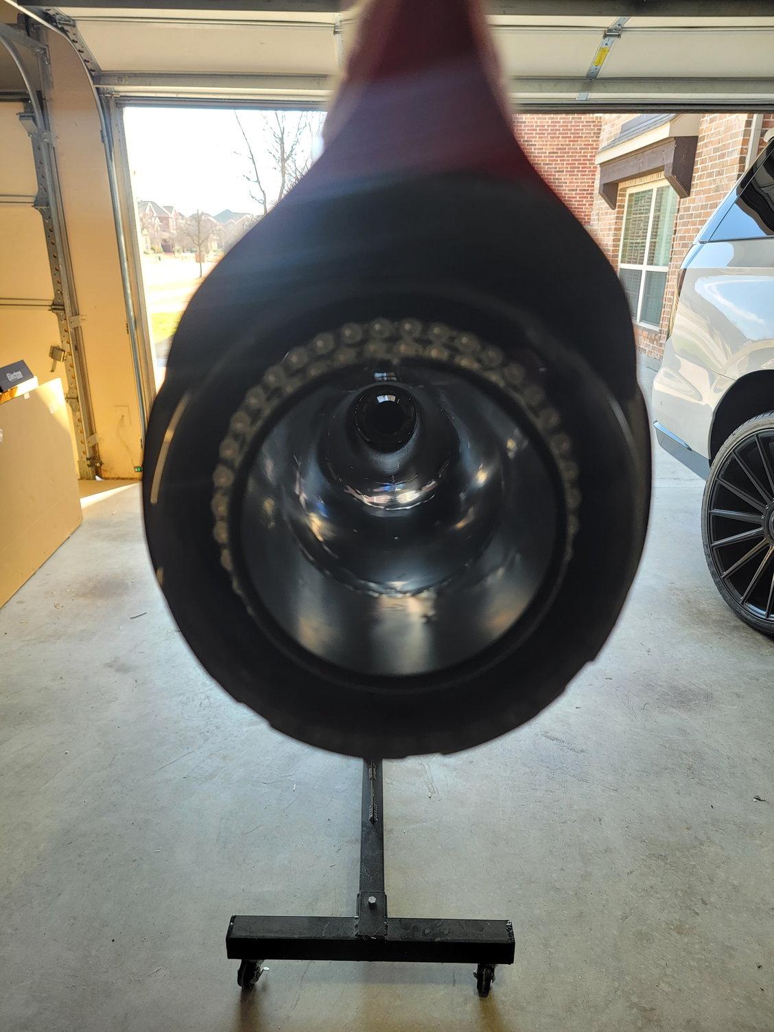
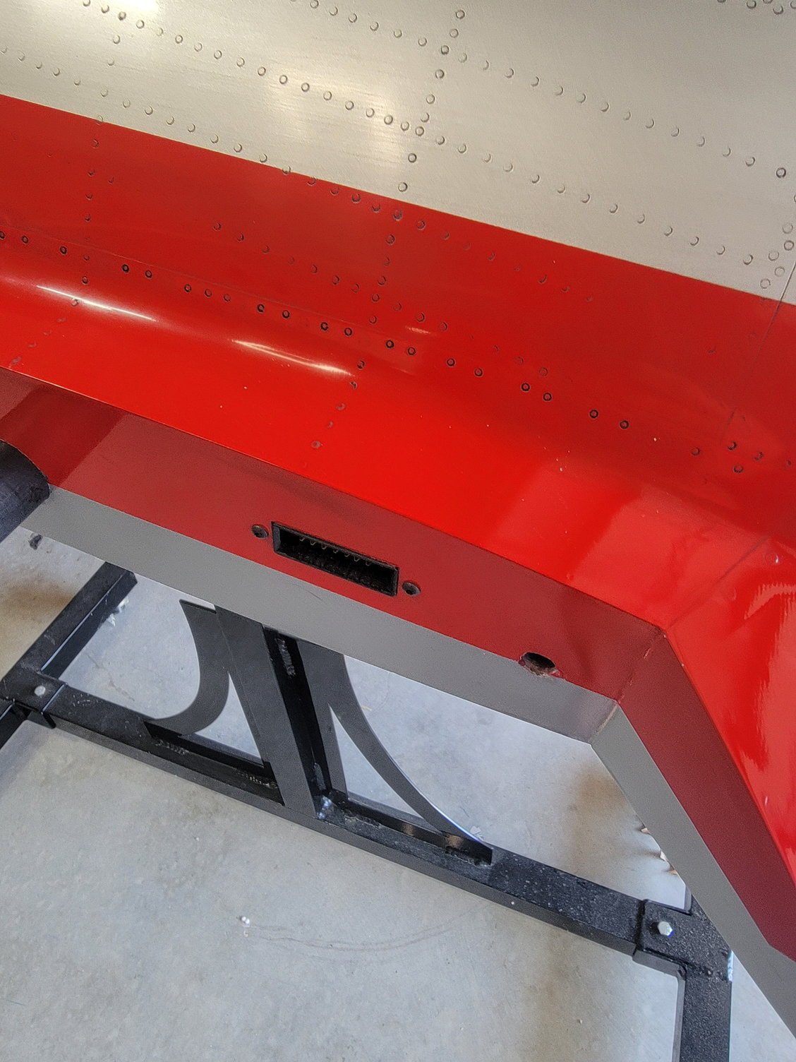
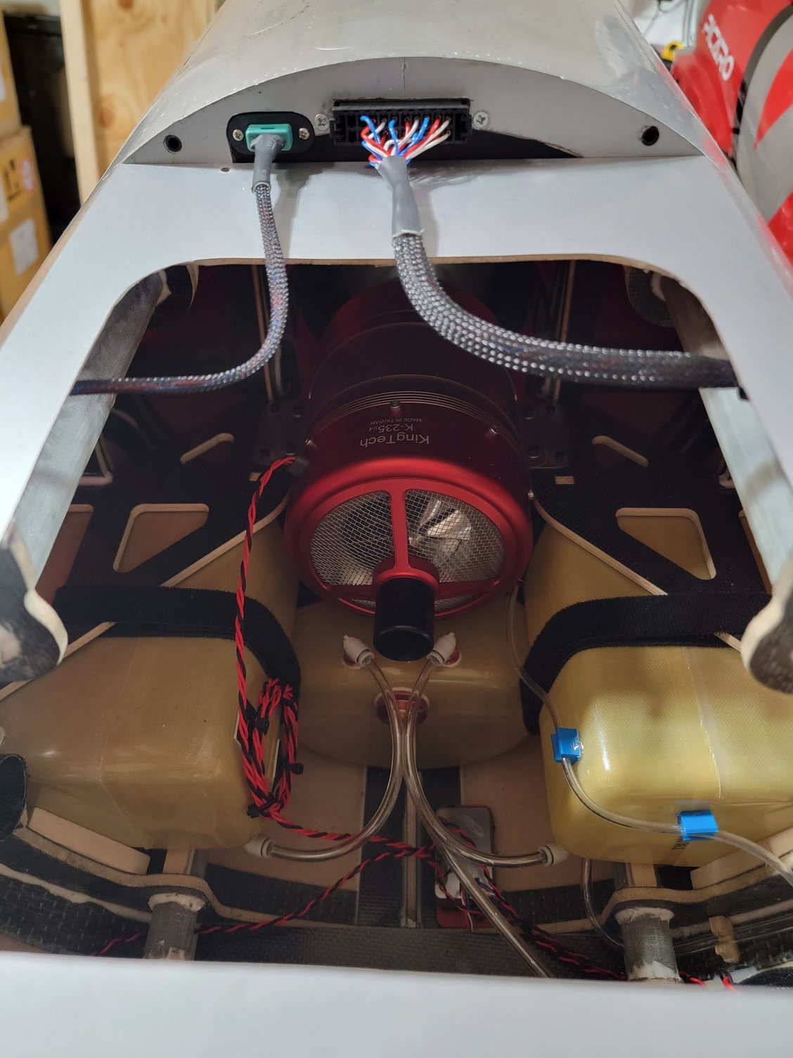
Made a little more progress today. Goal was to figure out how to get the pipe out and remove the air brakes. Pipe came out easily. It is well captured at the back as well as the front. All I did was remove the two bolts with a crescent wrench and 3mm ball Allen tool. To slip the pipe out I just pivoted it up and out along the top of the fuselage. Looked it over, dusted it off and found they marked "Top" on the bell mouth which is nice.
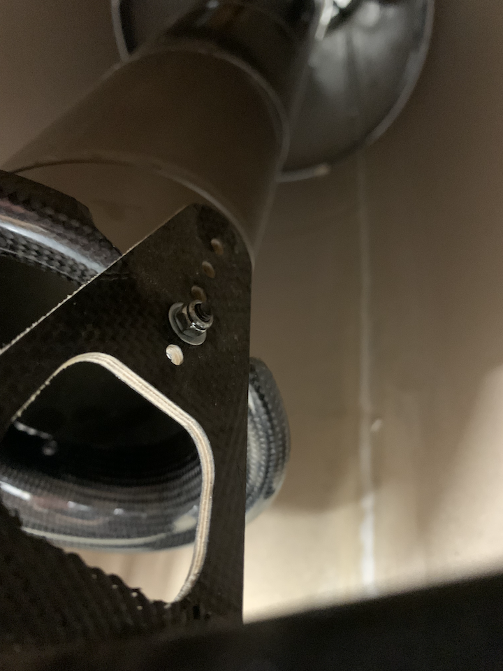
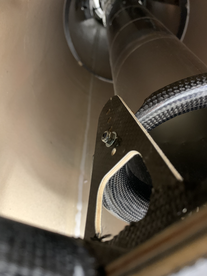
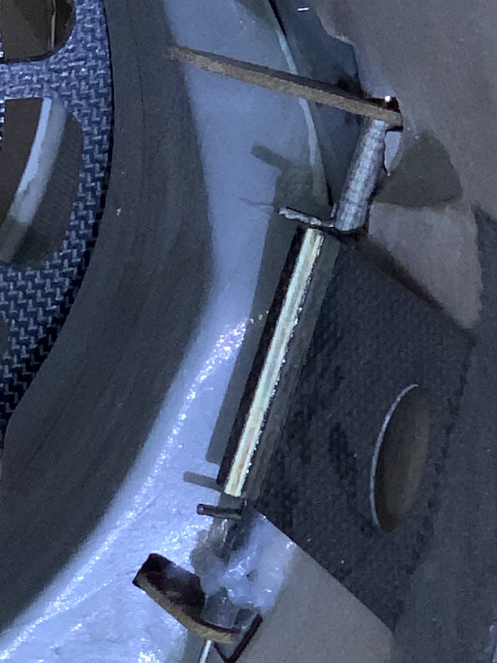
Next was to figure out how to remove the air brakes. At first it looked complicated, but after getting them out it seems very clever. A simple carbon fiber tube with some slots to guide the pins into position while a flap cut to the correct length keep the pins in the locked position. There really isn't a lot of room to service the airbrakes once the pipe is in, but I think one could do it at the field so long as the latter half of the fuse can be removed allowing access for pipe removal.
Here are some pictures of the disassembled parts:
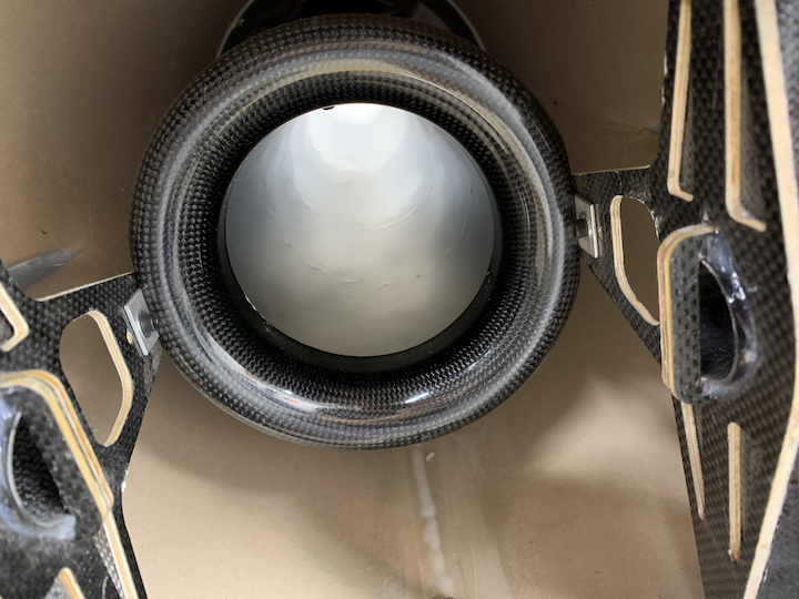
Pipe bell mouth close up
Right bolt mounting position, second hole, looking from the bell mouth side
Left bolt mounting position, second hole, looking from the bell mouth side
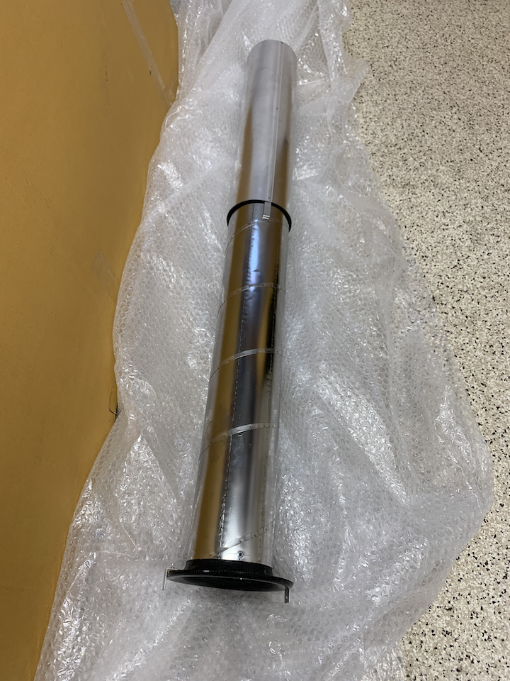
Removed pipe
Pipe marking
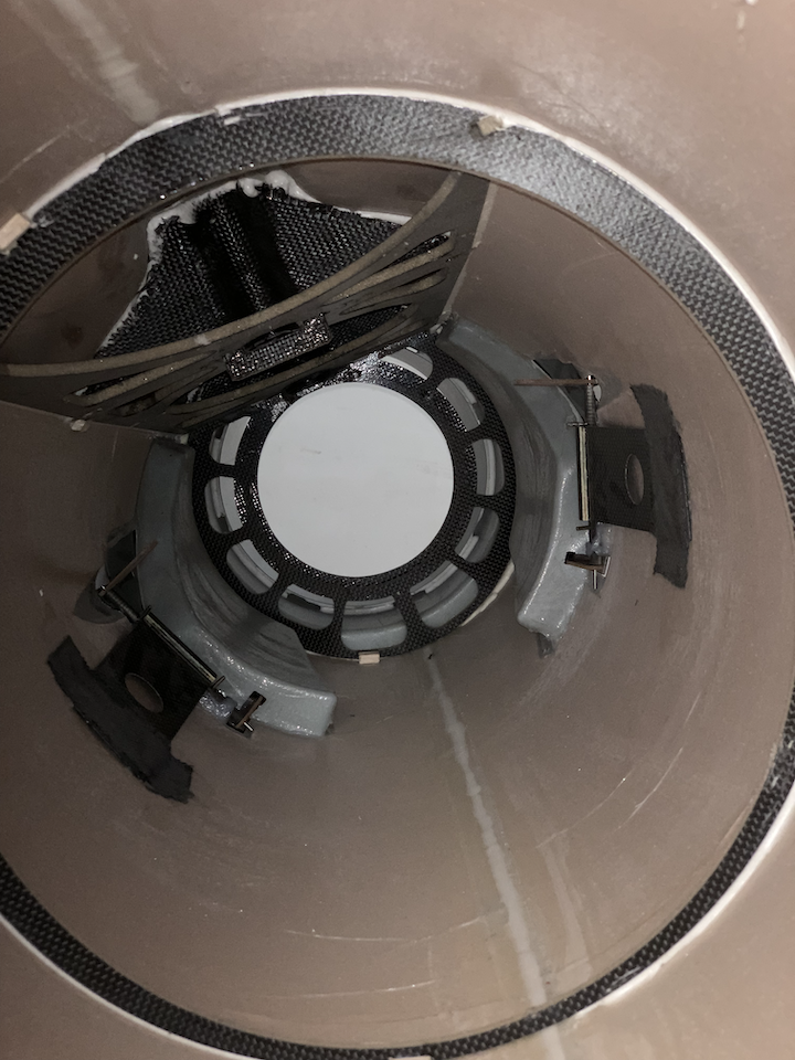
Close up of airbrake hinges
Airbrake hinge (close up)
Left airbrake horn
Airbrake hinge detail (close up)
Fuse detail of airbrake area
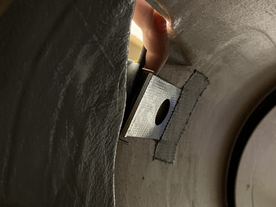
Flex plate and hinge detail
Airbrake (removed)
Additional fuse markings
Next was to figure out how to remove the air brakes. At first it looked complicated, but after getting them out it seems very clever. A simple carbon fiber tube with some slots to guide the pins into position while a flap cut to the correct length keep the pins in the locked position. There really isn't a lot of room to service the airbrakes once the pipe is in, but I think one could do it at the field so long as the latter half of the fuse can be removed allowing access for pipe removal.
Here are some pictures of the disassembled parts:
Pipe bell mouth close up
Right bolt mounting position, second hole, looking from the bell mouth side
Left bolt mounting position, second hole, looking from the bell mouth side
Removed pipe
Pipe marking
Close up of airbrake hinges
Airbrake hinge (close up)
Left airbrake horn
Airbrake hinge detail (close up)
Fuse detail of airbrake area
Flex plate and hinge detail
Airbrake (removed)
Additional fuse markings
 03-29-2022, 06:14 AM
#64
Senior Member
Shouldn't defend someone who openly attacks, groundlessly, and then doesn't do the right thing and apologize.
He's cost CARF a customer as a result, maybe more than one.
He's cost CARF a customer as a result, maybe more than one.
 03-29-2022, 07:05 AM
#66
Senior Member
He cost CARF a customer, period, and no, not this plane, but two others.
Instead, yesterday, skymaster got that money.
14000 in business that almost went to CARF....oops.
Instead, yesterday, skymaster got that money.
14000 in business that almost went to CARF....oops.
03-29-2022, 10:01 AM
#67
My Feedback: (1)
I cannot wait to see one of these up close. They are an incredible model.
I wouldn't bash CARF, the only thing bad is the length of time to get a new model from them. I'm waiting on one that I bought last summer.
And there is the old saying; Light, Strong or Cheap - pick any two.
The amount of abuse my poor little Rebel Hot has suffered and keeps going is amazing. (I need better thumbs)
03-30-2022, 12:01 PM
#69

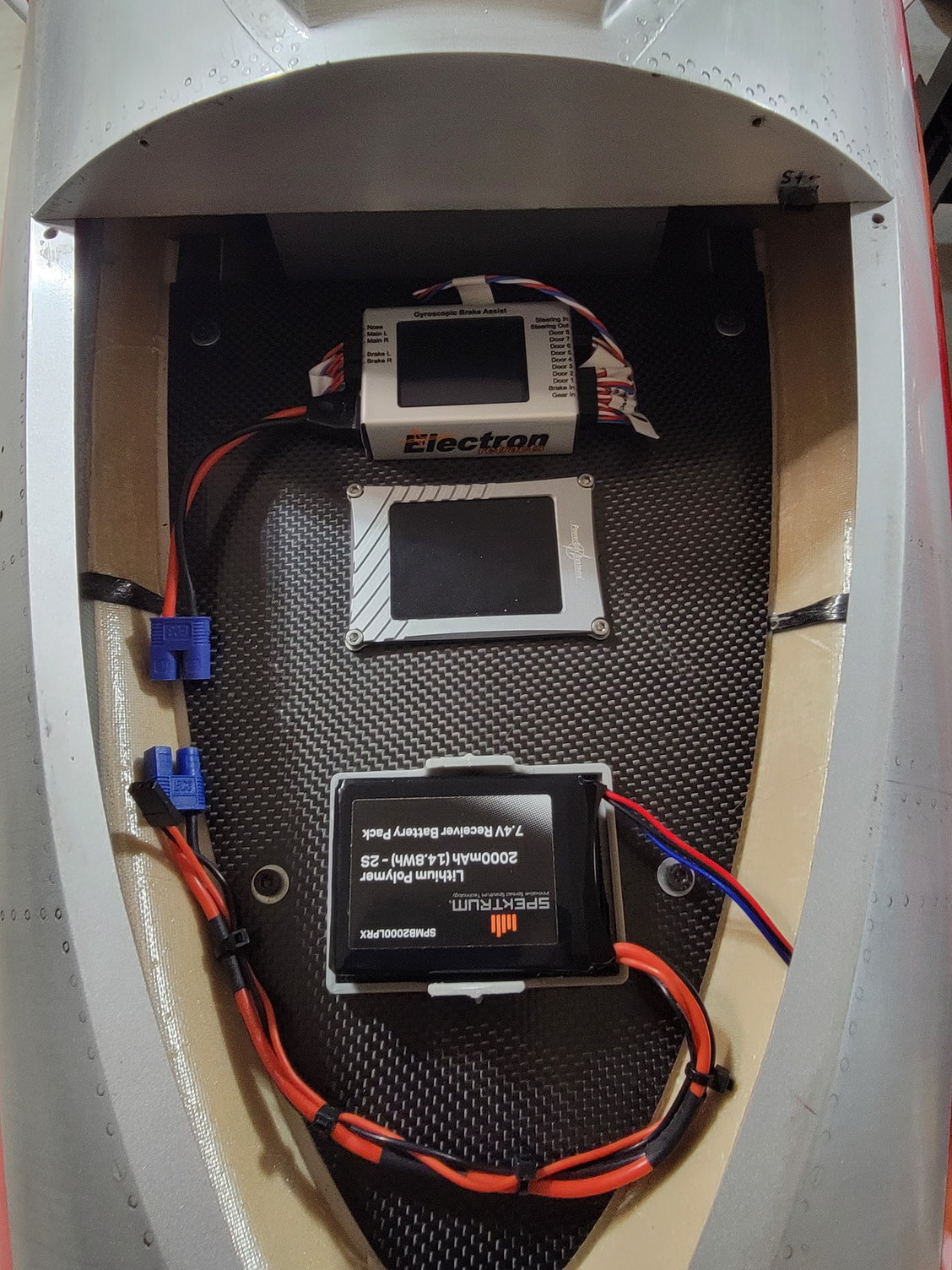
I sent measurements to Revoc for wing, stab, fin, and wing tank bags. I will have the test set here in a few days. Im thinking about a fuse bag as well.
Amazing quality on the MIG 17! Blown away.
I cant recommend the PNP option enough! Very high quality workmanship! definitely worth the expense. So Thankful I have this option!
Very impressive plane. I think the first of its kind regarding a competition level bespoke scale plane that is also PNP! You could take this plane straight to Top Gun type event and be at the top in static.
Well done Carf. Actually Superb!
Scott
Last edited by jetpilot; 03-30-2022 at 12:08 PM.

 04-01-2022, 06:08 PM
#73
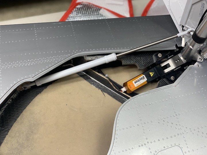
This took a little longer than I thought it would but managed to get the airbrakes installed. A lot happened during this portion of the build, but here's a short summary:
Mounting block parts (glued)
Mounting block with servo (test fit)
Mounting block parts (bottom view)

View with bolts assembled
Bottom view showing blots
Misc shot of servos with brackets
Airbrake closed position
Airbrake 45 degree position

Airbrake fully open
Push rod detail
Push rod length
Fuse preparation for gluing
Curved block to match the fuse shape
Completed servo and airbrake installation
Binding in this area, both sides (taken after sanding and touchup paint)
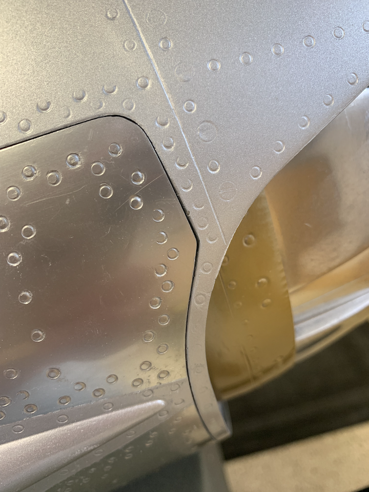
Close up of the binding area
- Built up the mounting blocks provided in the kit, lightly sanded the openings to get my servos to fit
- Sanded the base block to follow the shape of the fuse to maximize contact area for gluing
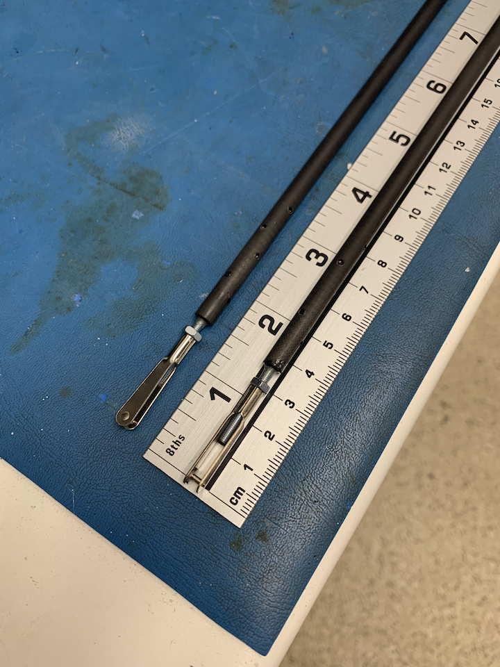
- Built up the push rods which came out to about 60cm in length
- My servo arm hole spacing for push rod attachment was a little off by a couple of mm (33mm vs 35mm per CARF recommendation)
- Prior to gluing the blocks down, I used double stick tape to check position and alignment with the airbrake horn
- The push rod length and servo arm position dictated the point where the blocks were to mount to the fuse, I drew an outline of the block with a pencil on the fuse to help aid in the gluing process
- I glued the blocks to the fuse one at a time so that I could rotate the fuse 90 degrees down to make it easy to align and add weight to the top of the assembly while glue dried
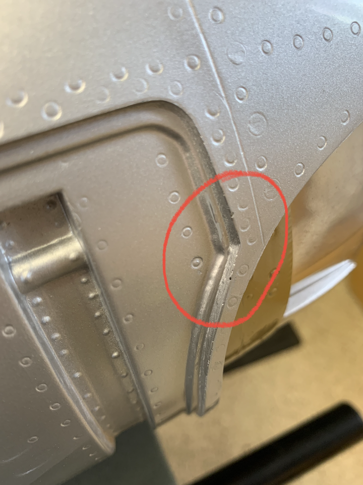
- Once everything was dry, I check servo arm travel and discovered I had some binding between the airbrake and fuse outline for the airbrake in a specific corner (see picture with red circle)
- I had to sand the inside of the airbrake and the fuse outline a bit to smooth out the airbrake deployment
- After sanding and touchup paint added I checked the operation with the transmitter, and all looked good
Mounting block parts (glued)
Mounting block with servo (test fit)
Mounting block parts (bottom view)
View with bolts assembled
Bottom view showing blots
Misc shot of servos with brackets
Airbrake closed position
Airbrake 45 degree position
Airbrake fully open
Push rod detail
Push rod length
Fuse preparation for gluing
Curved block to match the fuse shape
Completed servo and airbrake installation
Binding in this area, both sides (taken after sanding and touchup paint)
Close up of the binding area
04-08-2022, 01:48 PM
#74
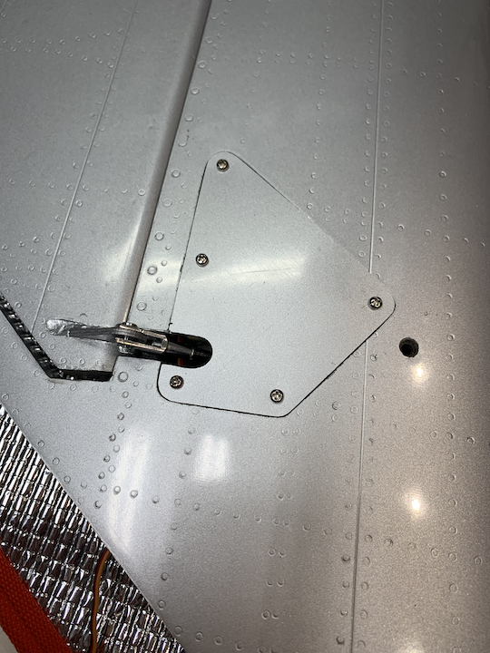
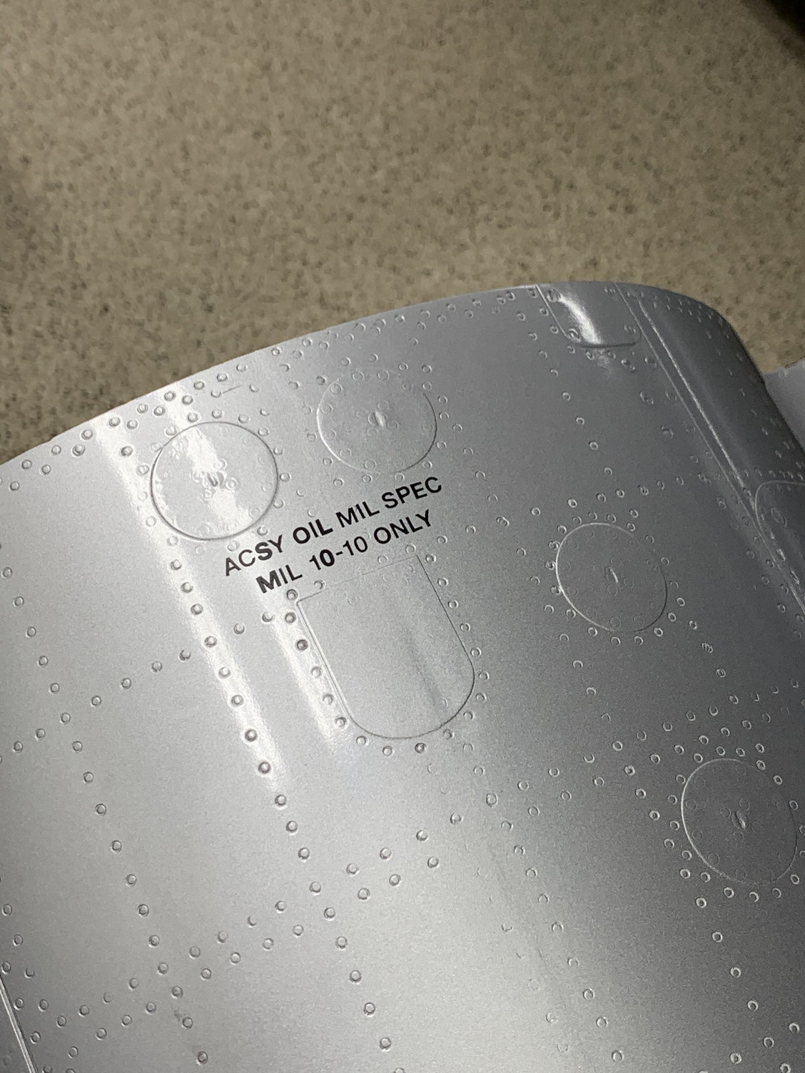
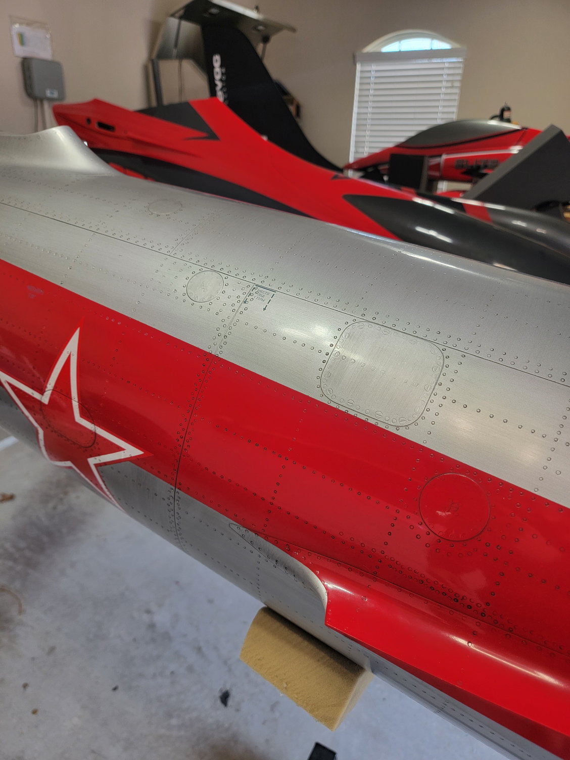
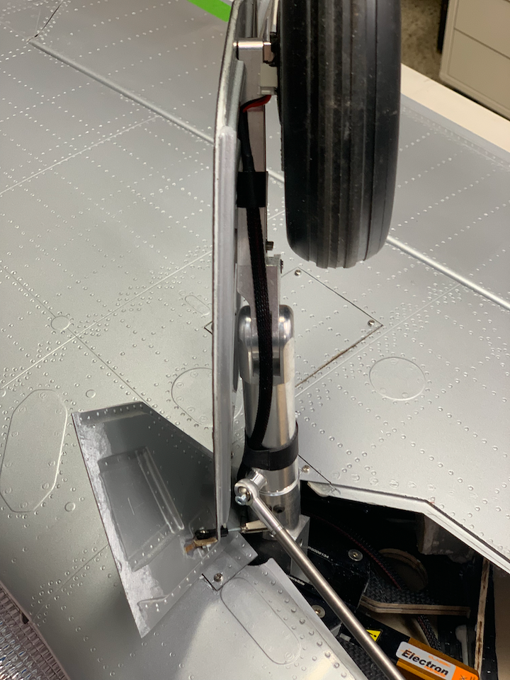
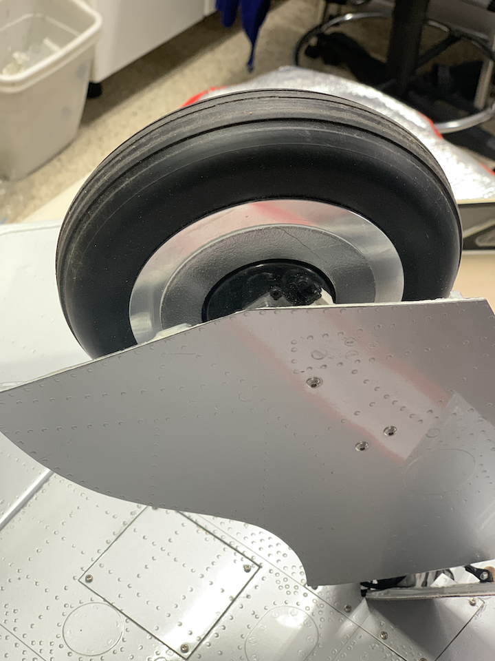
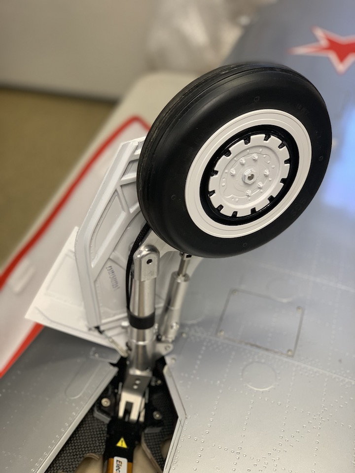
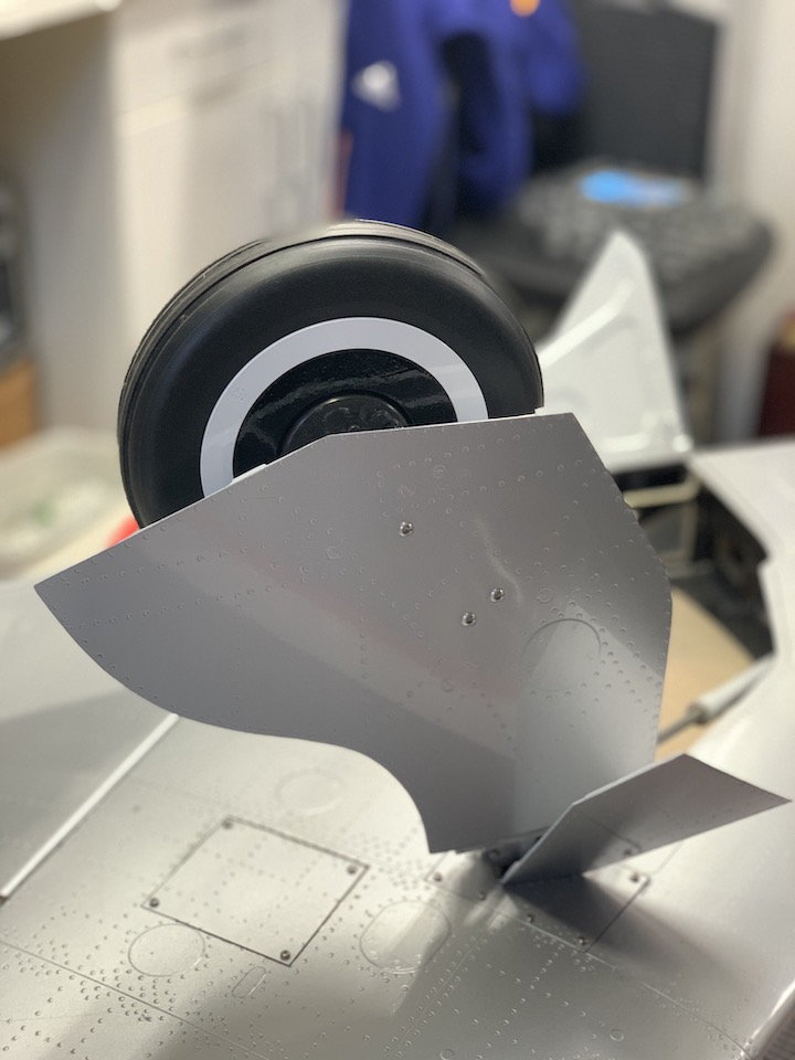
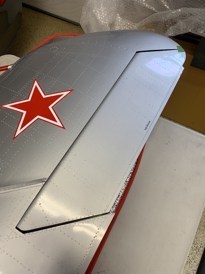
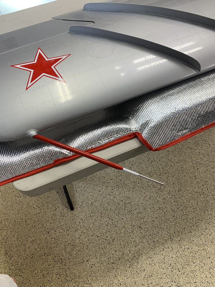
Pulled out the wings and began work on dressing up the doors, wheels, and tubes. One of the things I noticed right away when I first started handling the wings was how heavy they felt. So, I weighed them and each wing without the servos is ~8.4lbs. Started with painted the inside gear doors white. Needed to disassemble all the doors, which was not too hard. On mine the stock wheel rims and hubs come all silver, so I painted it to match the full scale. I'm reluctant to paint the struts white at this time as I didn't want to screwup the alignment from the factory and brake wire routing, plus there are a lot of set screws around the retract unit. Maybe after some successful flights I will revisit painting them. Added a little white on each of the wing tip tubes as well (left one for counterbalance while the right one a functional pitot like the full scale). Plan to start work on installing the servos next.
Stock main gear assembly
Stock main gear - outside view
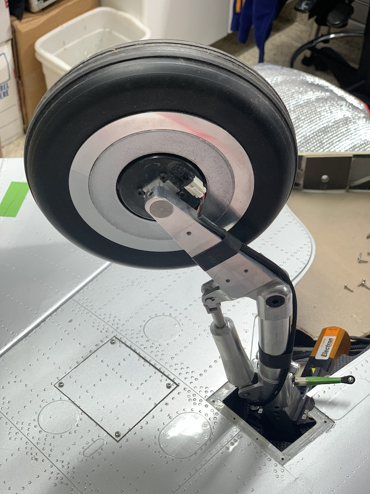
Stock main wheel and strut w/o door covers
Gear door - painted
Strut support rod
Strut with wheel removed
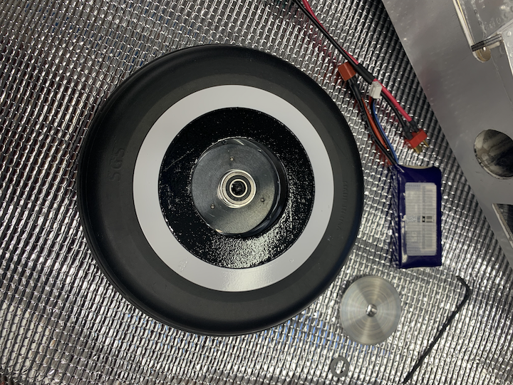
Main wheel with brake disk - painted (outside view)
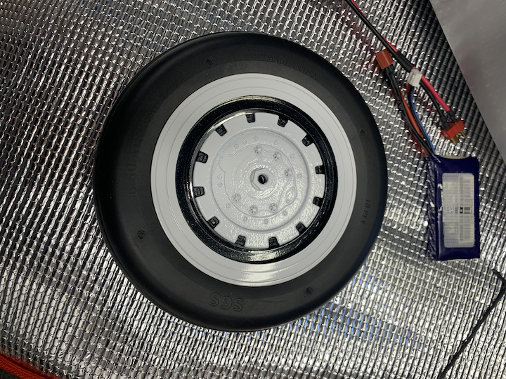
Main wheel - painted (inside view)
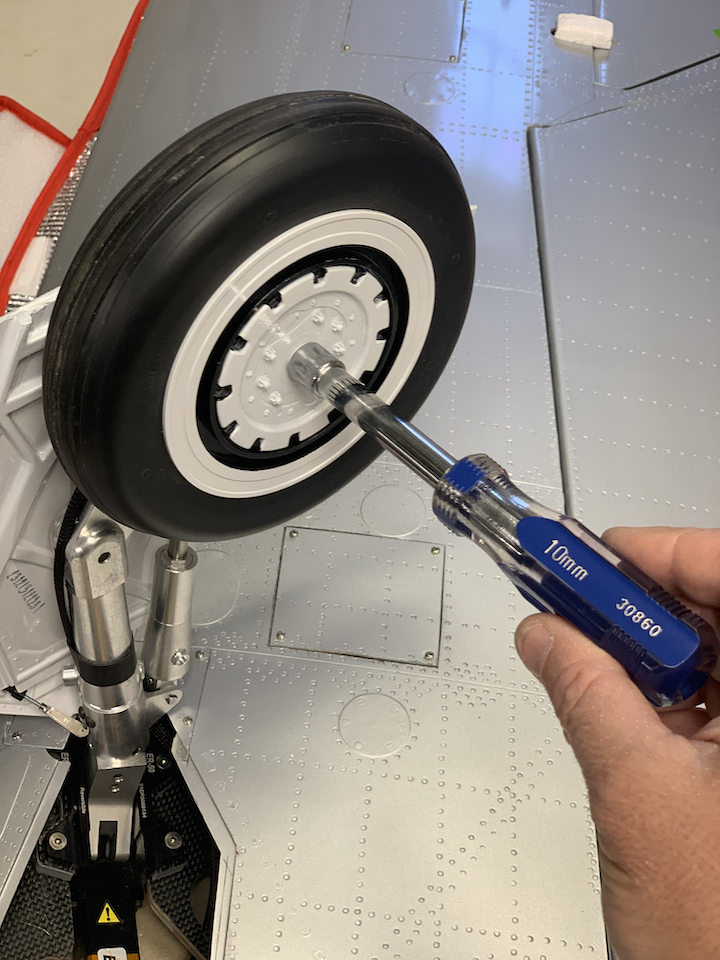
10mm nut driver
Close up - left main
Close up - left main
Close up - installed strut support rod
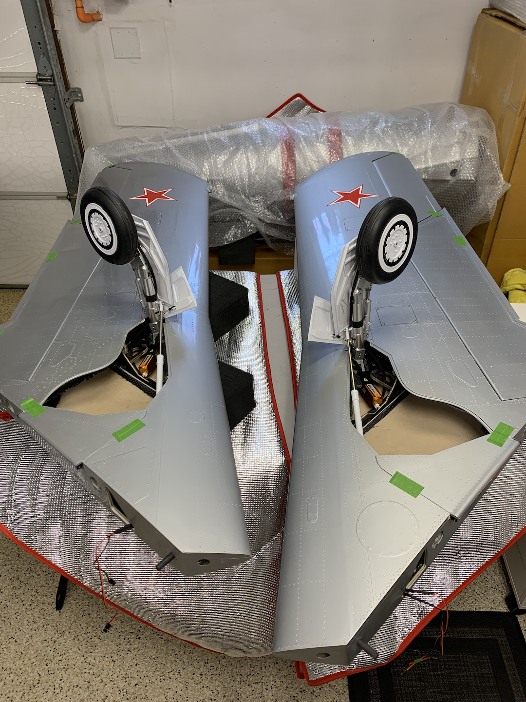
Both main gear deployed
Wing detail
Right aileron and note
Pitot tube - right wing
Stock main gear assembly
Stock main gear - outside view
Stock main wheel and strut w/o door covers
Gear door - painted
Strut support rod
Strut with wheel removed
Main wheel with brake disk - painted (outside view)
Main wheel - painted (inside view)
10mm nut driver
Close up - left main
Close up - left main
Close up - installed strut support rod
Both main gear deployed
Wing detail
Right aileron and note
Pitot tube - right wing
Last edited by Airforce7; 04-08-2022 at 01:49 PM. Reason: minor text edit
The following users liked this post:
jcterrettaz (04-08-2022)
04-08-2022, 01:50 PM
#75
Pulled out the wings and began work on dressing up the doors, wheels, and tubes. One of the things I noticed right away when I first started handling the wings was how heavy they felt. So, I weighed them and each wing without the servos is ~8.4lbs. Started with painting the inside gear doors white. Needed to disassemble all the doors, which was not too hard. On mine the stock wheel rims and hubs come all silver, so I painted it to match the full scale. I'm reluctant to paint the struts white at this time as I didn't want to screwup the alignment from the factory and brake wire routing, plus there are a lot of set screws around the retract unit. Maybe after some successful flights I will revisit painting them. Added a little white on each of the wing tip tubes as well (left one for counterbalance while the right one a functional pitot like the full scale). Plan to start work on installing the servos next.
Stock main gear assembly
Stock main gear - outside view
Stock main wheel and strut w/o door covers
Gear door - painted
Strut support rod
Strut with wheel removed
Main wheel with brake disk - painted (outside view)
Main wheel - painted (inside view)
10mm nut driver
Close up - left main
Close up - left main
Close up - installed strut support rod
Both main gear deployed
Wing detail
Right aileron and note
Pitot tube - right wing