


need iformation on old diesels
 07-09-2022, 04:03 AM
#51
Your suggestion/advice to free the contra works as the piston turns over now - thanks.
I bought a 11X5 but it does not fit as length of the prop hole into which the engine hub fits is too short, so may have to enlage the hole?
I bought a 11X5 but it does not fit as length of the prop hole into which the engine hub fits is too short, so may have to enlage the hole?
 07-17-2022, 10:41 PM
#52

Join Date: Jul 2005
Location: Upper HuttWellington, NEW ZEALAND
Posts: 1,601
Likes: 0
Received 1 Like
on
1 Post
OK-having seen the most recent photos-
(1) leave the contra alone-it is in a near enough to appropriate position for running-and if it wont move now, a bit of running should get things moving. By all means clean some of the gunge off the contra and the top of the cylinder and the underside of the head if you wish
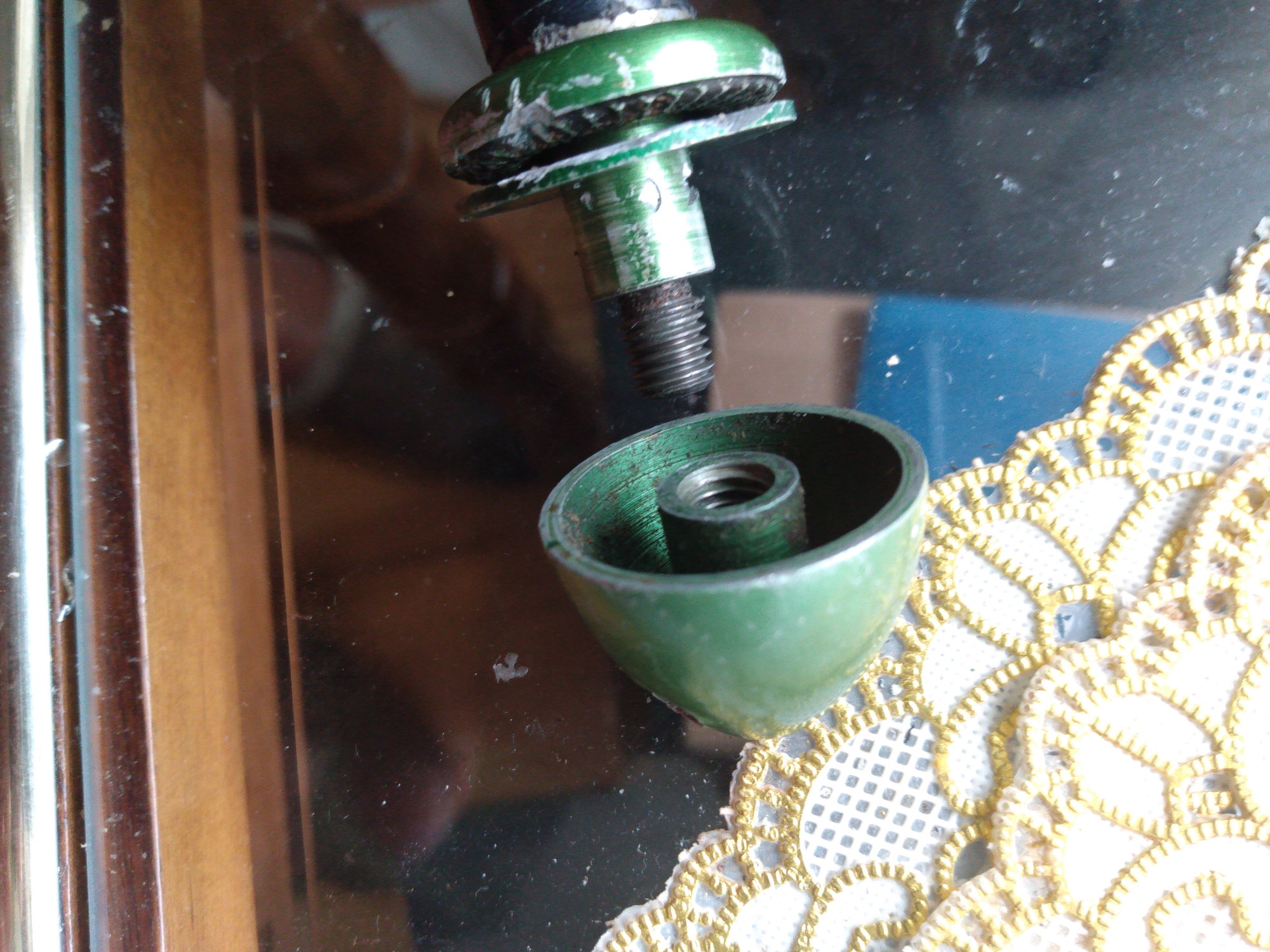
(2) the threaded section of the contra is irrelevant for our purposes-and has nothing to do with the engine's operation-it is how ED retained the contra when doing the grinding during manufacture-it was threaded on to a mandrel whilst the contra was ground to size. Most ED engines-regardless of size-and some from other manufacturers also have threads in this location.
(3) an 11x5 will be fine-the engine will probably turn this around 8-9000 rpm and produce a lot of static thrust doing so.
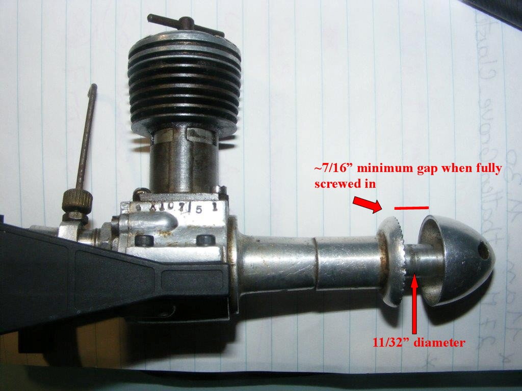
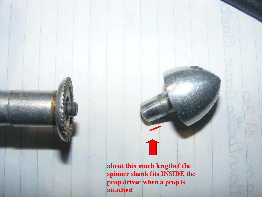
(4) prop attachment-look at the photos-the ED Hunter uses a 'sleeve nut' type of prop fixing-in which the shank screws OVER the crankshaft thread-but also INTO the centre recess of the prop driver. (not on your later model)This is simply a result of ED using good production economics (hardly surprising in the harsh days of immediate post war Britain!) and using some components from their ED MkIII 2.49cc engine in their MkIV 3.46cc-including the crankshaft, prop driver and spinner nut. You will have to bore out the centre hole of your 11x5 prop to 3/8" to clear the prop driver boss -if your prop hub is less than 7/16" in thickness you'll have to fit an additional washer or washers if the prop is loose, as when screwed fully home, the gap between the face of the prop driver, and the rear face of the spinner nut is about 7/16" Now normally I'd just use a prop reamer to do the hole-but I imagine you don't have one of those lying around so you'll have to do it with a twist drill-and I recommend you do it with a proper drill press, and not by hand-you want it to be concentric with the existing prop hole, and square to the prop axis. Depending on the brand of prop, you may have to drill it from the front side or the back side-depending on the blade shape-and perhaps use a piece of scrap wood underneath the hub so the blades are not contacting the drill press table, and the prop is sitting squarely. If it sits OK without a shim, fine. I imagine the existing hole will be 1/4" so you can enlarge it to 3/8" in a couple of successive steps using a 9/32", 5/16" , 11/32" and 3/8". Ideally it should be dead straight with respect to the hub, and a nice smooth fit on the stank of the spinner. Diesels vibrate a lot more than most glow engines, and a prop hub drilled off square will do nothing to help...!
Now yours is the later late 50s version with a slightly different shorter prop driver-but there are still a spinner and prop driver projecting boss to deal with-which will result in a minimum hub thickness-of about 7/16"...as with my photos, if the gap when the spinner nut is screwed fully home is larger than the prop hub thickness, you'll need to fit a washer-or even two, between the front of the prop and the back of the spinner nut to take up the slack. If it is thicker, no problem....
Once you've done that, you're pretty much in a situation to run it-providing you've got a) a fuel tank, b) some fuel, c) a fuel bottle of some sort and d) some fuel tubing......BTW DON"T use silicone fuel tubing-it doesn't work with diesels-the fuel makes it swell and it will come off any tank fittings and the needle assembly-you want either a clear plastic fuel line, or something like 'tygon' tubing
ChrisM
'ffkiwi'
(1) leave the contra alone-it is in a near enough to appropriate position for running-and if it wont move now, a bit of running should get things moving. By all means clean some of the gunge off the contra and the top of the cylinder and the underside of the head if you wish
(2) the threaded section of the contra is irrelevant for our purposes-and has nothing to do with the engine's operation-it is how ED retained the contra when doing the grinding during manufacture-it was threaded on to a mandrel whilst the contra was ground to size. Most ED engines-regardless of size-and some from other manufacturers also have threads in this location.
(3) an 11x5 will be fine-the engine will probably turn this around 8-9000 rpm and produce a lot of static thrust doing so.
(4) prop attachment-look at the photos-the ED Hunter uses a 'sleeve nut' type of prop fixing-in which the shank screws OVER the crankshaft thread-but also INTO the centre recess of the prop driver. (not on your later model)This is simply a result of ED using good production economics (hardly surprising in the harsh days of immediate post war Britain!) and using some components from their ED MkIII 2.49cc engine in their MkIV 3.46cc-including the crankshaft, prop driver and spinner nut. You will have to bore out the centre hole of your 11x5 prop to 3/8" to clear the prop driver boss -if your prop hub is less than 7/16" in thickness you'll have to fit an additional washer or washers if the prop is loose, as when screwed fully home, the gap between the face of the prop driver, and the rear face of the spinner nut is about 7/16" Now normally I'd just use a prop reamer to do the hole-but I imagine you don't have one of those lying around so you'll have to do it with a twist drill-and I recommend you do it with a proper drill press, and not by hand-you want it to be concentric with the existing prop hole, and square to the prop axis. Depending on the brand of prop, you may have to drill it from the front side or the back side-depending on the blade shape-and perhaps use a piece of scrap wood underneath the hub so the blades are not contacting the drill press table, and the prop is sitting squarely. If it sits OK without a shim, fine. I imagine the existing hole will be 1/4" so you can enlarge it to 3/8" in a couple of successive steps using a 9/32", 5/16" , 11/32" and 3/8". Ideally it should be dead straight with respect to the hub, and a nice smooth fit on the stank of the spinner. Diesels vibrate a lot more than most glow engines, and a prop hub drilled off square will do nothing to help...!
Now yours is the later late 50s version with a slightly different shorter prop driver-but there are still a spinner and prop driver projecting boss to deal with-which will result in a minimum hub thickness-of about 7/16"...as with my photos, if the gap when the spinner nut is screwed fully home is larger than the prop hub thickness, you'll need to fit a washer-or even two, between the front of the prop and the back of the spinner nut to take up the slack. If it is thicker, no problem....
Once you've done that, you're pretty much in a situation to run it-providing you've got a) a fuel tank, b) some fuel, c) a fuel bottle of some sort and d) some fuel tubing......BTW DON"T use silicone fuel tubing-it doesn't work with diesels-the fuel makes it swell and it will come off any tank fittings and the needle assembly-you want either a clear plastic fuel line, or something like 'tygon' tubing
ChrisM
'ffkiwi'
Last edited by ffkiwi; 07-17-2022 at 10:56 PM.
 07-23-2022, 09:23 PM
#54
Join Date: Jul 2005
Location: Upper HuttWellington, NEW ZEALAND
Posts: 1,601
Likes: 0
Received 1 Like
on
1 Post
this is turning into a bigger saga than 'War and Peace'-I can give you advice based on more than 5 decades of hands on experience with engine-including the exact make and model that you have-but I cannot make you understand-that requires effort on YOUR part.
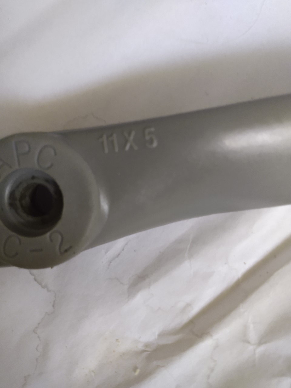
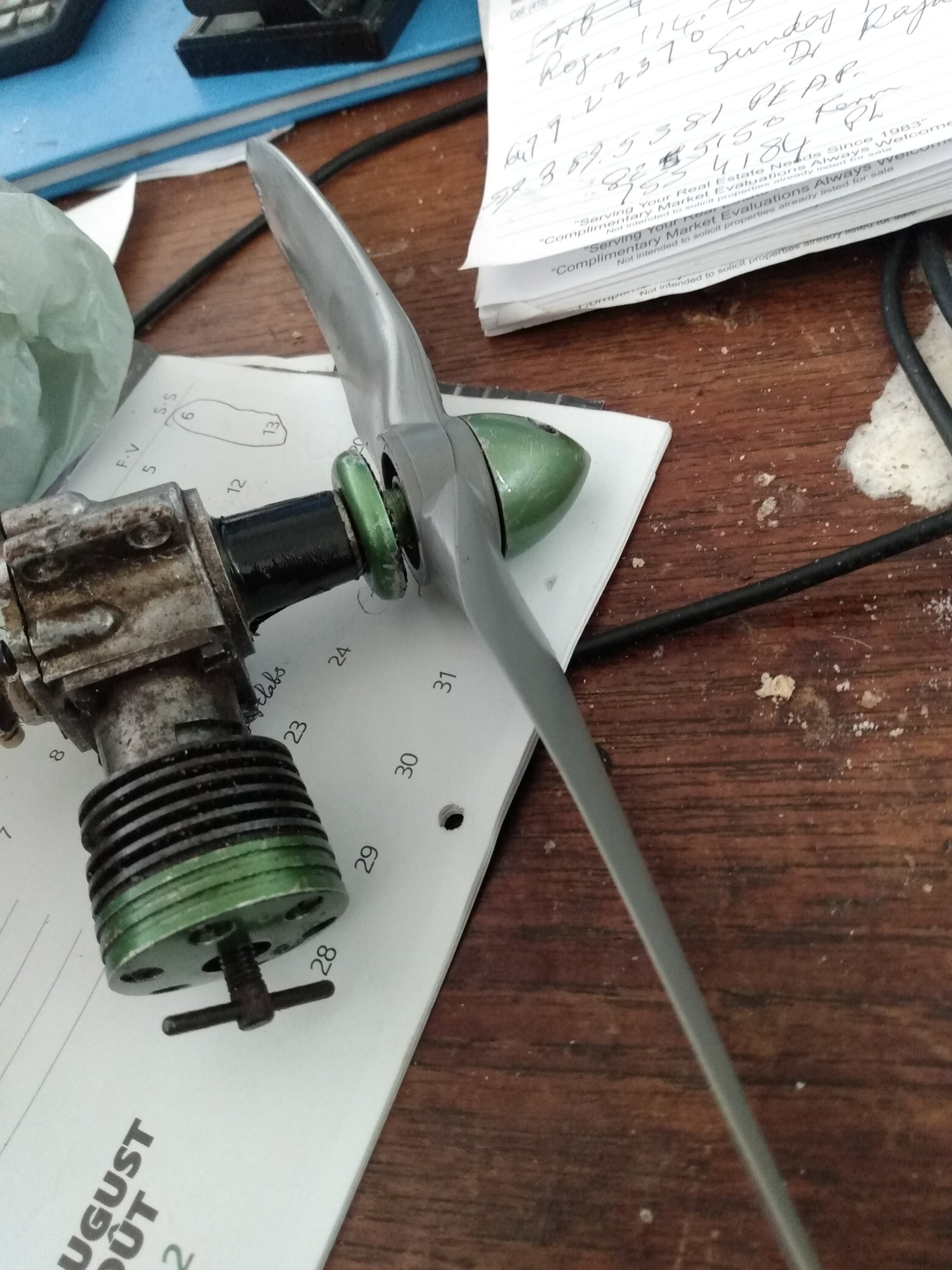
You have an APC propellor-measuring some of mine, of similar size , the hub thickness measures around 12mm-so exceeds the 7/16' minimum clearance on your Hunter when the spinner is screwed on-that means you will not have to worry about extra packing washers between the front of the prop and the rear of the spinner-in other words you will be able to do everything up tight when the prop is fitted. look at the photos-the APC prop comes with a stepped diameter propellor shaft hole in the hub-6.25mm on the front face and 8mm on the rear face. This is still too small to clear the projecting centre boss on the engine's prop driver-which is a nominal 3/8" diameter-or a fraction over 9.5mm -but it projects a full 10mm from the front of the prop driver-so the prop will have to be drilled out to a clearance fit on the prop driver boss-I previously suggested you do this in stages, so as not to end up off centre. Drilling off centre and/or off perpendicular will aggravate any vibration effects when the engine is running.
If you had a piloted reamer like I mentioned in an earlier post, this is quite easy, but lacking a tool like this you will have to use a succession of drills -preferably in a drill press-to enlarge the centre hole until it will fit on the engine. My drills run in 1/64" increments in the imperial sizes, and in 0.5mm increments in metric. If you can lay your hands on one-then a 9.6mm drill would give just the right clearance to fit the prop driver spigot comfortably without being too tight. The 9.6mm (or imperial equivalent) hole will have to go all the way through the propellor hub, as the prop driver boss extends most of the way through the hub (from the rear face)-and will finish about 2mm below the front face of the prop hub when the prop is positioned on the shaft and in contact with the prop driver. Then its simply a case of screwing the spinner on, and tightening it. The traditional positioning of the prop is at 'twenty to two' as the engine come on compression-when viewed from the front of the engine-or putting it another way, when you start to feel compression resistance as you rotate the prop anti clockwise, the prop should be about 20-30 degrees off the vertical, again viewed from the front-and also this is for a right handed person. If you are left handed you will have to come up with a propellor position that suits you by trial and error.
ChrisM
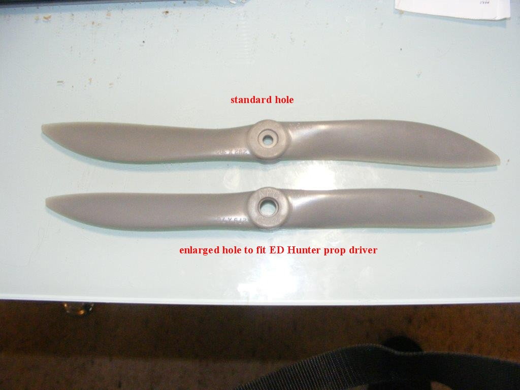
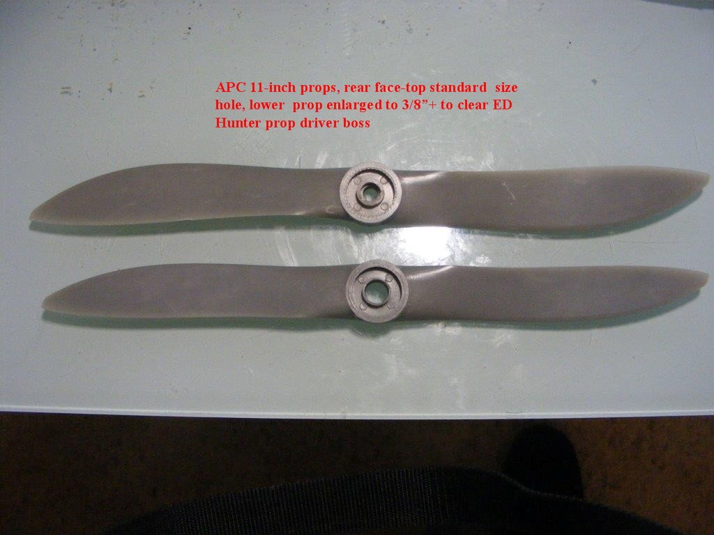
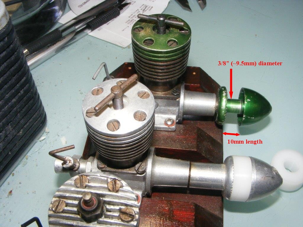
 07-24-2022, 01:35 PM
#56
Join Date: Jul 2005
Location: Upper HuttWellington, NEW ZEALAND
Posts: 1,601
Likes: 0
Received 1 Like
on
1 Post
I have to ask at this point-do you have ANY previous experience operating ANY type of model engine?-because I cannot understand why you have difficulty in grasping the most basic things like installing a propeller-if the answer is 'no' then you have been simply wasting my time these past few months-and this engine is quite unsuitable for someone without experience unless they are under the direct physical supervision of someone who is experienced.
ChrisM
'ffkiwi'
ChrisM
'ffkiwi'
The following users liked this post:
peterburford (07-24-2022)
 07-28-2022, 07:04 AM
#58
Got the prop attached. Now about to try and restart the engine. Instead of pure ether, I got the spray can from John Deere that contains ether but that is hard to insert into the mix of kerosene and castor oil. Any ideas as to how to solve this?
07-28-2022, 09:37 AM
#59

Yes. Decant the ether from the spray can into a jar with a top. I use a 16oz wide mouth canning jar with ring and lid. I drill a few small holes in the lid big enough for an aerosol spray can straw. I found another spray can top from a can of Brake cleaner that fit the ether can. Put the straw into the jar and spray until you get the amount of liquid out of it you need. I marked my jar with 1 fluid ounce graduations. Fill to the line, add to your fuel can/bottle with other ingredients, and shake.. it does help to chill the ether cans in the freezer for a couple hours to slow the evaporation of the ether.
07-28-2022, 05:59 PM
#60
Join Date: Jul 2005
Location: Upper HuttWellington, NEW ZEALAND
Posts: 1,601
Likes: 0
Received 1 Like
on
1 Post
ChrisM
,ffkiwi'
07-30-2022, 03:44 AM
#62
Member
Blimey...
Anyways, the engine assembled turns over now ?
Either buy an engine mount, or source some wood/5 ply and make your own.
I assume you have a work space with a vice to hold the wood, and made engine mount, to make the engine mount and hold the made engine mount firmly for an engine test run ?
Do not ( DO NOT !!!!! ) Grip the engine in a vice !!!!!!!
Suitable screws or bolts with nuts and washers ( better than screws In a home made engine mount ) to hold engine via its mounting "beams" into the wood engine mount.
Measure the engine "width" , between it's beams, and cut the wood to accommodate the engine, a u shape.
The wood should be long enough to fit full width in the vice jaws and leave sufficient length to clear engine sticky outy bits.
Even a small plastic empty pill container will suffice for a fuel tank, held in place by elastic bands or better.
The top of the tank, and fuel level, should be slightly below the level of the engine spray bar, that being the brass bit with the needle valve and fuel pipe stub.
In the spray bar, can you see any fuel holes when looking down into the "Venturi", the bit/hole that allows air, and fuel mixture into the engine ?
No, is good but check the spray bay is clear/not blocked, and the fuel holes are clear.
So with the engine firmly mounted into its mounting, and the mounting firmly held in a vice, full fuel tank at correct hieght with tubing attached, needle valve lightly screwed home then unscrewed 2 to 3 turns, cover Venturi with finger and turn engine over 2 or 3 times and watch fuel being drawn into spray bar...
May be 1 or 2 drops of fuel dropped into Venturi and test engine turns over, not flooded, the "flicking" can begin...
Don't not let the engine flood with fuel, do not ( DO NOT ) use an electric starter !!!!
A good engine on good fuel ( model technics D1000 ) that is fresh, properly set up, in warmish weather above 10degrees c, usually will burst into life after 3 flicks or so...
Post a picture of the engine as it is now, and when fitted into a vice mounted engine mount...
Over to you sir....
Ps, properly set up, working compression screws system, needle valve setting, fuel and fuel hieght etc.....
08-25-2022, 01:02 PM
#63
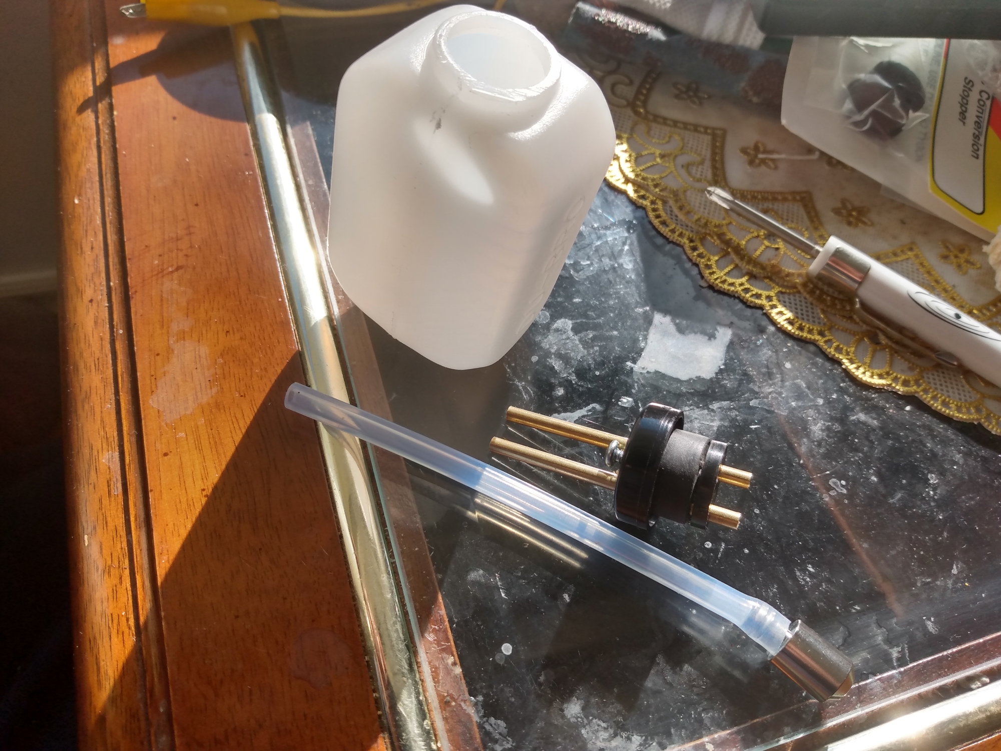
Here is a pic of my "fuel tank"; not happy with it, plastic and quite thin, so looking to change it. Also, here is a pic of the engine mounted on the work-bench. Now am almost ready to go. Not sure if a fuel bottle is also req'd?
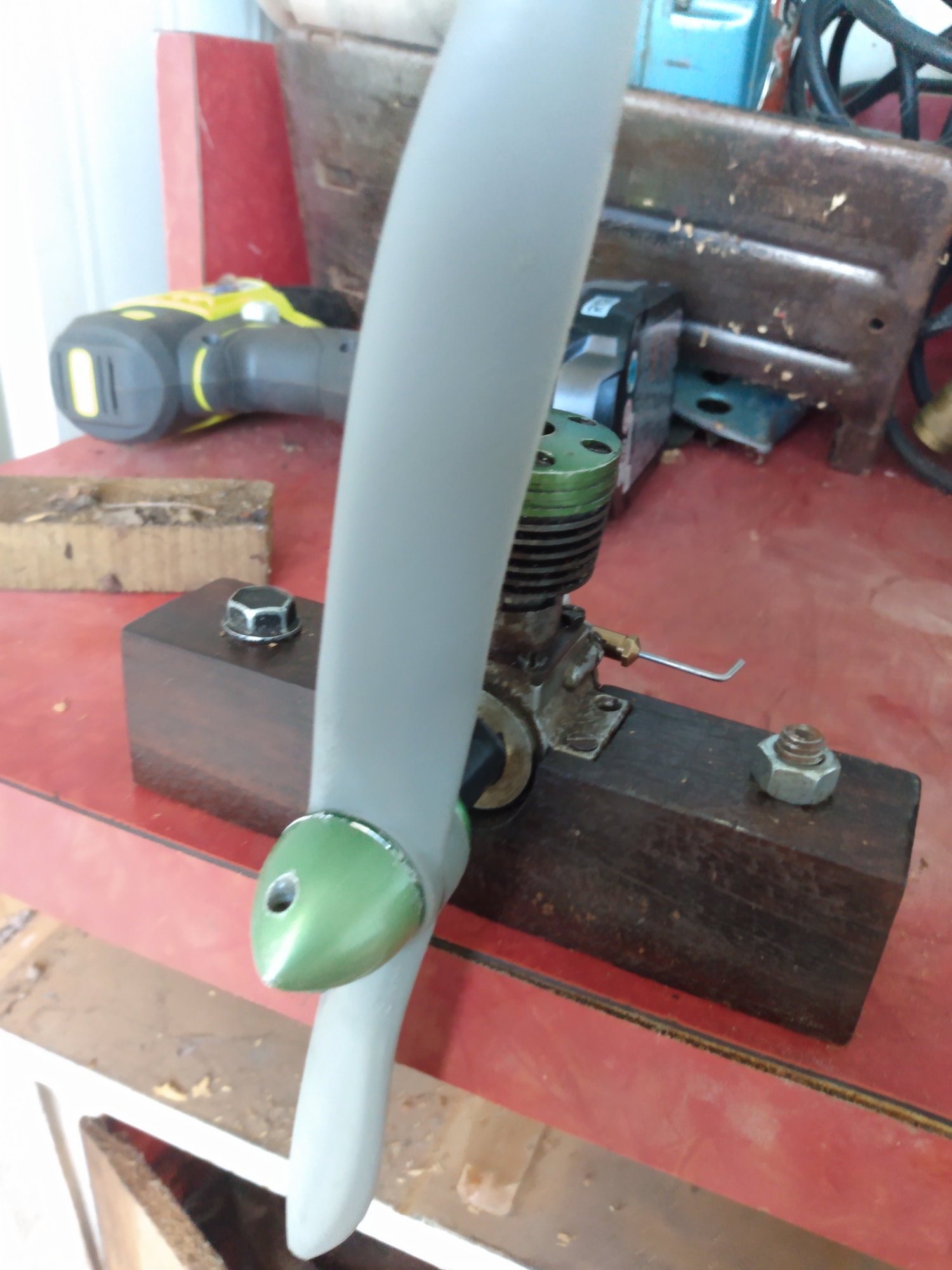
engine on work bench
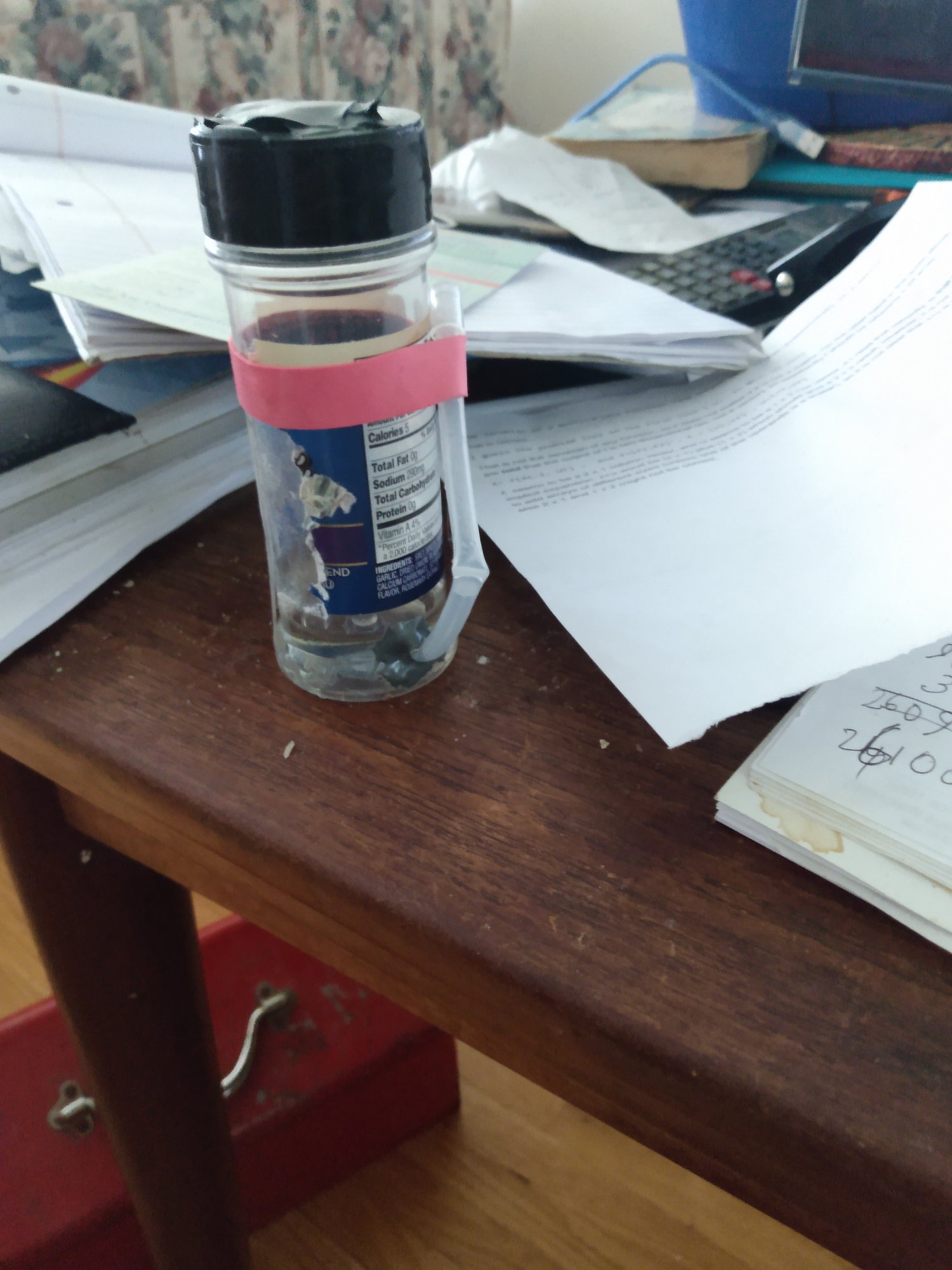
"fuel tank"
engine on work bench
"fuel tank"

 10-30-2022, 04:58 PM
#67
 11-01-2022, 11:31 AM
#71
Member
Did you make the engine mount ?
Recessed for the engine...
I wonder why the engine crankcase has 4 holes for screws/bolts ?
We're the holes countersunk when you got the engine ?
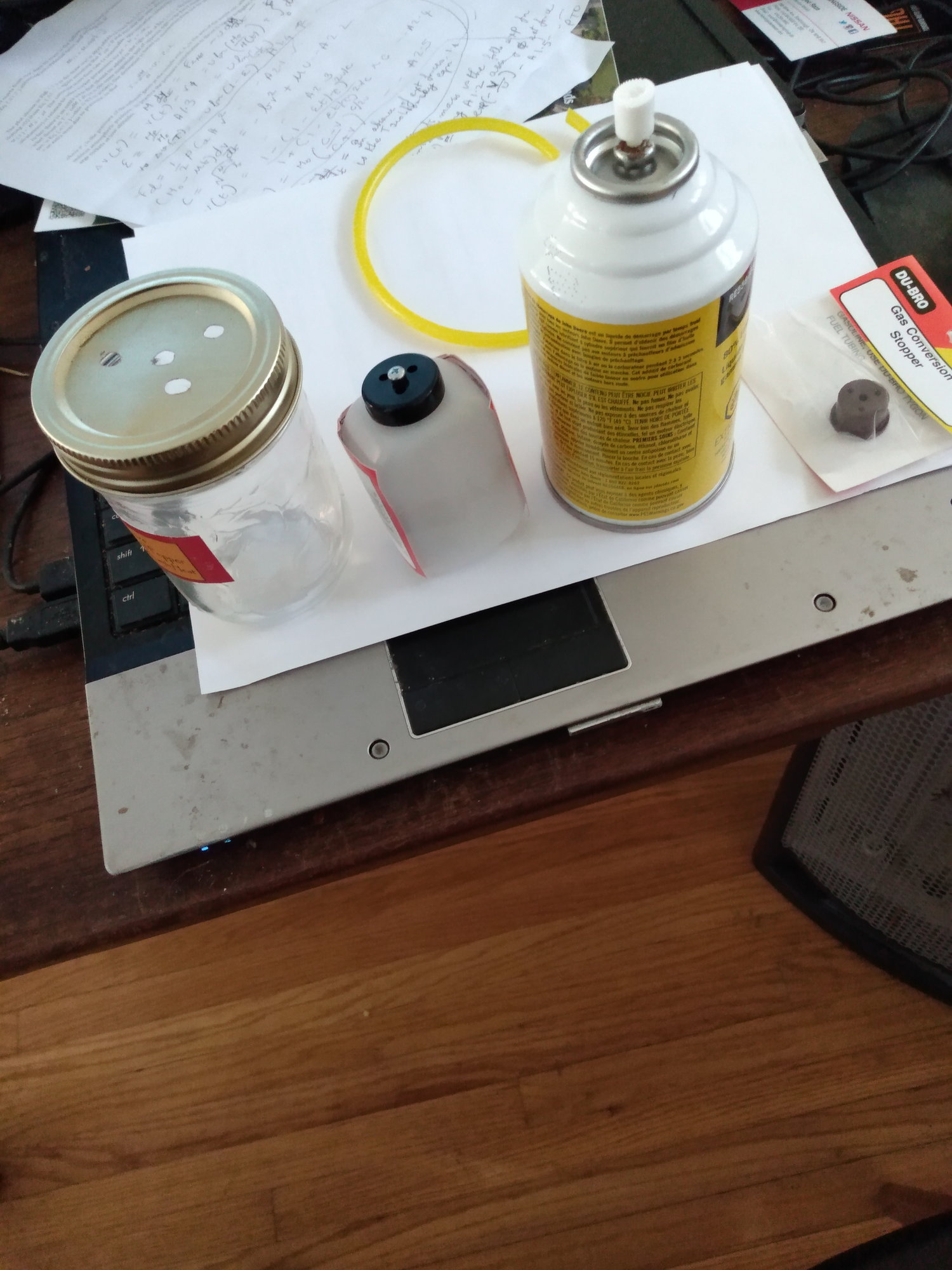
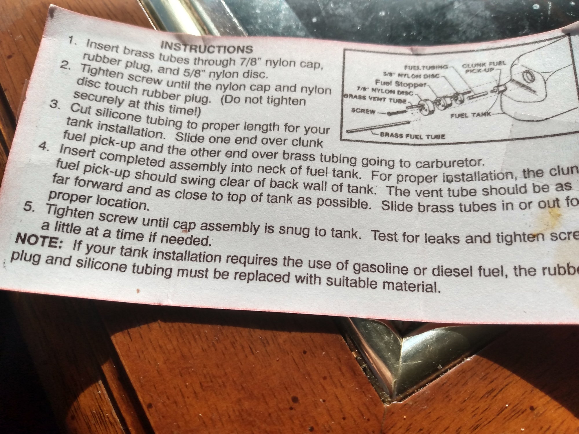
I have a tank just like that but cannot remember if I used it for a diesel ( compression ignition ). The tube with the clunk looks like glow fuel tube so needs to be changed for tube suitable for diesel fuel.
Have you sanded the rather sharp edges of the prop ?
I see this engine has a rear "carb"...
I have not checked on sceptreflight web site, but this engine may have a "Rotory induction valve" sleeve rather than a reed valve. ?
Go to sceptreflight and check.
Do not attempt to start this engine untill you have sorted engine screws, fuel tubing etc., Prop, and induction method.
Pictures.....
Ps I wonder if the fuel needle valve is a PAW one ?
Recessed for the engine...
I wonder why the engine crankcase has 4 holes for screws/bolts ?
We're the holes countersunk when you got the engine ?
I have a tank just like that but cannot remember if I used it for a diesel ( compression ignition ). The tube with the clunk looks like glow fuel tube so needs to be changed for tube suitable for diesel fuel.
Have you sanded the rather sharp edges of the prop ?
I see this engine has a rear "carb"...
I have not checked on sceptreflight web site, but this engine may have a "Rotory induction valve" sleeve rather than a reed valve. ?
Go to sceptreflight and check.
Do not attempt to start this engine untill you have sorted engine screws, fuel tubing etc., Prop, and induction method.
Pictures.....
Ps I wonder if the fuel needle valve is a PAW one ?
11-01-2022, 11:41 AM
#72
Member
Pps,
do not attempt to start this engine until "helpers" on here have seen all your pictures, further pictures may be requested, for clarity etc..
A pictures tells 1000 words.
We can see stuff you may not be aware of.
Once helpers give an "ok" you should be reasonably ok to attempt and engine start.
Remember we do this stuff from a distance rather than standing next to you.
I'm off to sceptreflight now, have you checked on there yet ?